I A J
WARNING: TO AVOmD SERIOUS iNJURY, BEFORE PERFORMING ANY SERVICE OR ADJUSTMENTS:
° Depress brake pedal fully and set parking brake.
° P_aee attachment clutch in "DmSENGAGED" position.
° Turn ignition key to "STOP" and remove key.
" Make sure the blades and all moving parts have completely stopped.
" Disconnect spark plug wire from spark plug and place wire where it cannot come incontact with plug.
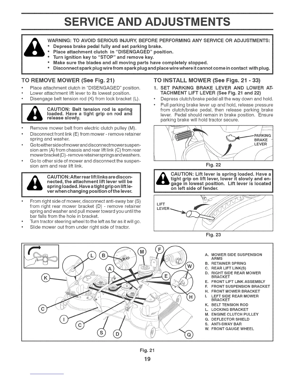
TO REMOVE MOWER (See Fig. 21)
Place attachment clutch in "DISENGAGED" position.
Lower attachment lift lever to its lowest position.
Disengage berettension rod (K) from lock bracket (L).
1 _ CAUT,ON: Belt tensionrodisspring 1
loaded. Have a tight grip on rodand |
U re_ease s_ow_y.
o Remove mower beretfrom electric clutch pulley (M).
Disconnect front link (E) from mower =remove retainer
spring and washer.
Goto eitherside ofmower anddisconnectmowersuspen=
sion arm (A) from chassis and rear lift link (0) from rear
mower bracket (D)=remove retainersprings and washers.
Go to other side of mower and disconnect the suspen=
sion arm and rear lift link.
TO iNSTALL MOWER (See Figs. 21 - 33)
1. SET PARKING BRAKE LEVER AND LOWER ATo
TACHMENT LiFT LEVER (See Fig. 21 and 22)
o Depress clutch/brake pedal all the way down and hold.
o Pull parking brake lever up and hold, release pressure
from clutch/brake pedal, then remease parking brake
lever. Pedal should remain in brake position. Ensure
parking brake will hold tractor secure.
Fig. 22
&
CAUTNON:After rear lift _inksare discon-
nected, the attachment lift _ever will be
spring _oaded. Have aright grip on Hft _e-
vet when changing position of the lever.
From right side of mower, disconnect anti-sway bar (S)
from right rear mower bracket (D) = remove retainer
spring and washer and pull mower toward you until the
bar falls from the hole in bracket.
Turn tractor steering wheel to the left as far as it will go.
Slide mower out from under right side of tractor.
on meftside of fender.
UFT
Fig. 23
[
Ao MOWER SiDE SUSPENSION
ARMS
Bo RETAINER SPRING
C. REAR LiFT LINK(S)
D° RIGHT SiDE REAR MOWER
BRACKET
E. FRONT LiFT LiNK ASSEMBLY
E FRONT SUSPENSION BRACKET
Ho FRONT MOWER BRACKET
L LEFTSIDE REAR MOWER
BRACKET
K° BELT TENSION ROD
L° LOCKaNG BRACKET
M° ENGINE CLUTCH PULLEY
Q° DEFLECTOR SHIELD
S. ANTra-SWAY BAR
Wo FRONT GAUGE WHEEL
Fig. 21
19