I A J
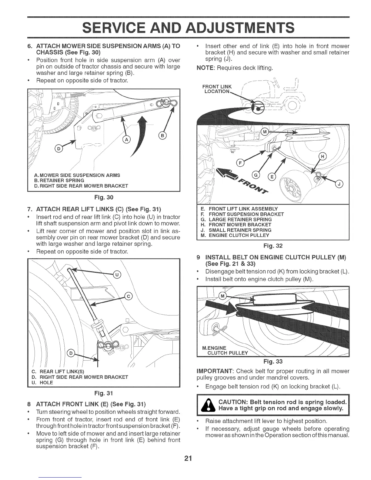
6. ATTACH MOWER SIDE SUSPENSION ARMS (A) TO
CHASSIS (See Fig. 30)
o Position front hole in side suspension arm (A) over
pin on outside of tractor chassis and secure with large
washer and large retainer spring (B).
Repeat on opposite side of tractor.
/
; /
/ /
;/
/
/
A. MOWER SiDE SUSPENSION ARMS
B. RETAINER SPRING
D° RIGHT SiDE REAR MOWER BRACKET
Fig. 30
7. ATTACH REAR LIFT LINKS (C) (See Fig. 31)
Insert rod end of rear lift link (C) into hole (U) in tractor
lift shaft suspension arm and pivot link down to mower.
Lift rear corner of mower and position slot in link as-
sembly over pin on rear mower bracket (D) and secure
with large washer and large retainer spring.
Repeat on opposite side of tractor.
C. REAR LIFT LINK(S)
Do RIGHT SiDE REAR MOWER BRACKET
U° HOLE
Fig. 31
8 ATTACH FRONT MNK (E) (See Fig. 31)
Turn steering wheeJ to position wheels straight forward.
o From front of tractor, insert rod end of front link (E)
through front hole in tractor front suspension bracket (F).
Move to left side of mower and and insert large retainer
spring (G) through hole in front link (E) behind front
suspension bracket (F).
Insert other end of link (E) into hole in front mower
bracket (H) and secure with washer and small retainer
spring (J).
NOTE: Requires deck lifting.
E° FRONT UFT UNK ASSEMBLY
E FRONT SUSPENSION BRACKET
G. LARGE RETAINER SPRING
H° FRONT MOWER BRACKET
J° SMALL RETAINER SPRING
M° ENGINE CLUTCH PULLEY
Fig. 32
9 LNSTALL BELT ON ENGmNE CLUTCH PULLEY (M)
(See Fig. 21 & 33}
o Disengage belt tension rod (K) from locking bracket (L).
o InstalJ belt onto engine clutch pulley (M).
M.ENGINE
CLUTCH PULLEY
Fig. 33
iMPORTANT: Check belt for proper routing in alJ mower
pulley grooves and under mandrel covers.
Engage belt tension rod (K) on locking bracket (L).
i CAUTmON: Be_t tension rod is spring loaded. 1
_IL Have a tight grip on rod and engage slowly.
Raise attachment lift lever to highest position.
If necessary, adjust gauge wheels before operating
mower as shown inthe Operation section ofthis manual.
21