8 Rev. 3.0 13/06/16
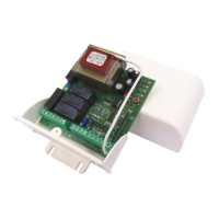
LRX 2218 electronic control unit
An electronic control unit for the automation of 4 motors for roll-
ing window shutters and/or sun blinds, with optional connection
of Wind, Sun and Rain Sensors and use with pushbutton con-
trol panel and radio control for individual and centralised con-
trol.
- Mod. LG 2218 : Without radio receiver
- Mod. LRS 2218 : 433.92 MHz
- Mod. LRS2218 SET: “Narrow Band” 433.92 MHz
- Mod. LRH 2218 : “Narrow Band” 868.3 MHz
T
ECHNICAL
S
PECIFICATIONS
- Power supply: 230V~ 50/60Hz 1700W max.
- Motor output: 230V~ 400W Max.
- Working temperature: -10 to 55°C
- Radio receiver: see model
- Compatible radio controls: 12-18 Bit - Rolling Code
- Nr possible radio controls: 60 Max.
- Nr possible wireless sensors: 3 Max.
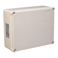
- Packaging dimensions: 190x140x70 mm.
- Container: ABS UL94V-0 ( IP65 )
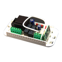
C
ONNECTION OF
CN1
T
ERMINAL
B
OARD
15: ~230V line input (Phase).
16: ~230V line input (Neutral).
17: Motor 1 Upward movement output.
18: Motor 1 Shared output.
19: Motor 1 Downward movement output.
20: Motor 2 Upward movement output.
21: Motor 2 Shared output.
22: Motor 2 Downward movement output
23: Motor 3 Upward movement output.
24: Motor 3 Shared output.
25: Motor 3 Downward movement output
26: Motor 4 Up output.
27: Motor 4 Shared output.
28: Motor 4 Downward movement output.
C
ONNECTION OF
CN2
T
ERMINAL
B
OARD
13: U1 Upward movement Local Input (NO).
14: GND shared Signal Input
15: D1 Downward movement Local Input (NO).
16: U2 Upward movement Local Input (NO).
17: GND shared Signal Input
18: D2 Downward movement Local Input (NO).
19: U3 Upward movement Local Input (NO).
20: GND shared Signal Input
21: D3 Downward movement Local Input (NO).
22: U4 Upward movement Local Input (NO).
23: GND shared Signal Input
24: D4 Downward movement Local Input (NO).
CN3
T
ERMINAL
B
LOCK
C
ONNECTIONS
15: 24 Vac Sun Sensor Power Output
16: “S” Sun Sensor Input (NO).
17: GND shared Input / 0 Vac Output
18: “R” Rain Sensor Input (NO).
19: GND shared Input
20: “W” Wind Sensor Input.
21: UZ Upward movement Zone Input (NO).
22: GND shared Input
23: DZ Downward movement Zone Input (NO).
24: UG Upward movement General Input (NO).
25: GND shared Input
26: DG Downward movement General Input (NO).
27: Antenna Input.
28: Antenna hot pole Input.
I
NITIAL
O
PERATING
C
ONDITION
The control unit allows you to control the 4 motors independent-
ly using the Local U1-2-3-4 (Up) or D1-2-3-4 (Down) controls,
and the UZ (Up zone), DZ (Down zone) and general UG (Up)
and DG (Down) simultaneous control keys. It is also possible to
control the 4 motors together or independently using one or
more radio controls. In the default configuration the control unit
has no radio control stored on its memory.
FUNCTIONAL PROPERTIES:
Operation with Local Control or Zone Keys:
Connection to the U1-U2-U3-U4-UZ and D1-D2-D3-D4-DZ low
voltage inputs of the local control keys (normally open) for run-
ning the shutter will ensure the following operation:
U1-U2-U3-U4-UZ control raising for the configured motor time,
D1-D2-D3-D4-DZ control lowering of the shutter; sending a
command for the same direction before the motor stops run-
ning, the control unit stops the shutter; sending a command for
the opposite direction before the motor stops running, the con-
trol unit reverses the movement.
Operation with General Keys:
The following type of operation is obtained by connecting the
general command buttons (normally open) for movement acti-
vation to the low voltage inputs UG – DG:
UG controls upward movement until the motor running time has
elapsed and DG controls downward movement. If a command
is sent in the same direction before the motor running time has
elapsed, the control unit will ignore the command; if a com-
mand is sent in the opposite direction before the motor running
time has elapsed, the control unit will invert the direction of the
motor.
O
PERATION WITH DIFFERENT
R
ADIO CONTROLS
It is possible to program different models of radio control: stor-
ing a code (1 key) obtains Step by step cyclical operation (Up –
Stop – Down), storing two different codes (2 keys) obtains dif-
ferent commands – the first for Raising and the second for
Lowering; storing a BeFree radio control (3 keys) obtains sepa-
rate commands – the first key for Raising, the second for Stop-
ping and the third for Lowering.
Operation using a 1-key radio control:
Using the radio control with single key ensures the following
operation: the first press controls the upward movement for the
configured motor time. The second press controls downward
movement of the shutter; if the key is pressed before the motor
stops running, the control unit stops the shutter, another press
of the key reactivates the motor in the opposite direction.
Operation using a 2-key radio control:
Using the radio control with 2 keys ensures the following opera-
tion: the first key (“Up” for raising) controls upward movement
of the shutter for the configured motor time and the second key
(“Down” for lowering) controls downward movement of the shut-
ter. If another Up command is sent while the shutter is being
raised, the control unit continues to raise it; whereas if a Down
command is sent, the control unit stops the motor.
The procedure is the same for the Down movement phase.
Operation using a 3-key radio control (BeFree x1):
Using the BeFree x1 radio control ensures the following opera-
tion: the (Up) key controls upward movement of the shutter for
the configured motor time, the (Stop) key stops operation and
the (Down) key controls downward movement of the shutter. If
a (Stop) command is sent while the shutter is being raised or
lowered, the control unit stops the motor. If a command is sent
that is in the opposite direction, the control unit causes the
shutter to change direction.
 Loading...