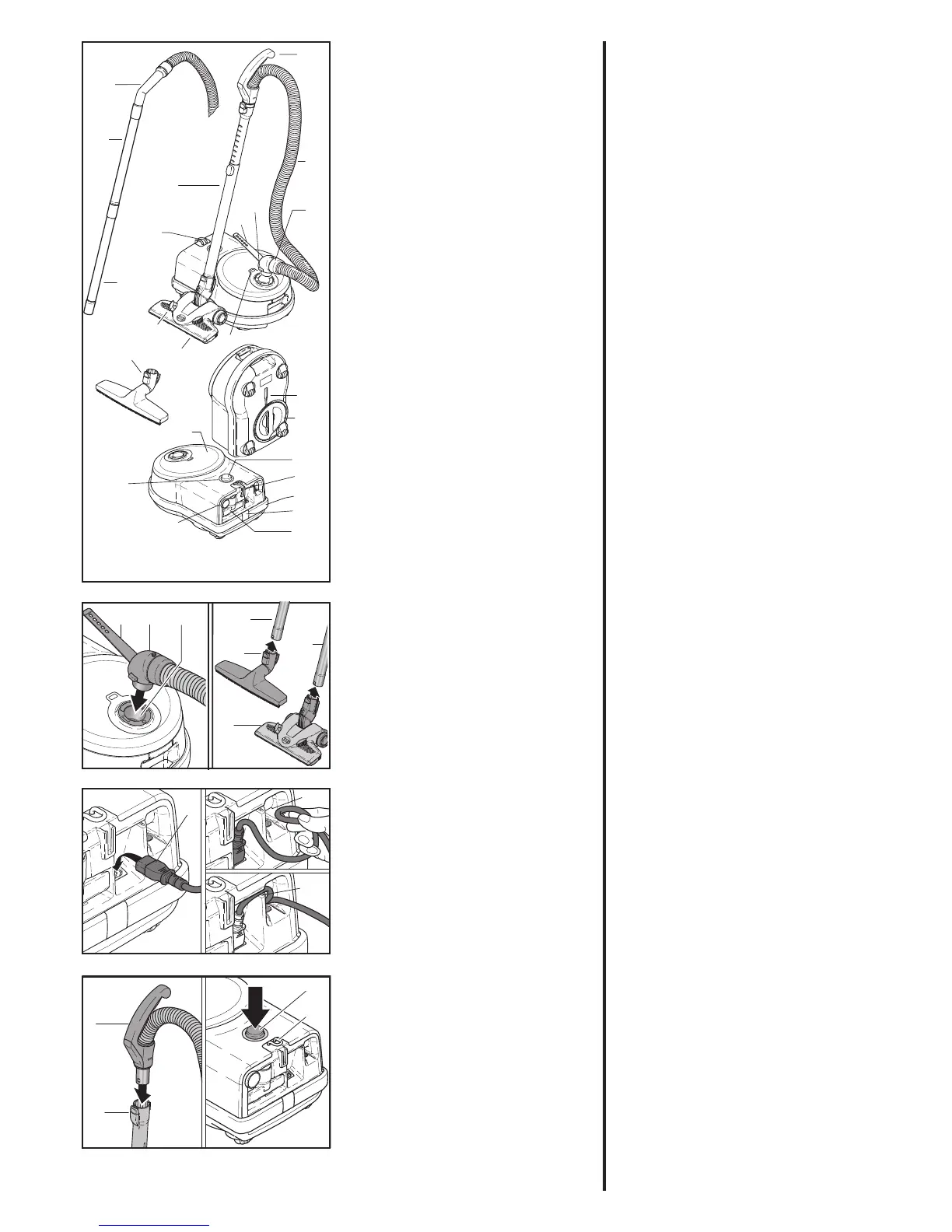
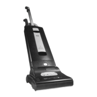
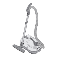
3. Gerätebeschreibung
1 SEBO KOMBI*
2 Fußschieber*
5a Edelstahl-Teleskoprohr*
5b Edelstahl-Steckrohr*
6a Handgriff*
6b Handgriff*
7 Schlauch
8 Schlauchstutzen
8a Lasche
9 Knopf
10 Schaltknopf mit
Leistungsregulierung
11 Betriebsanzeige
12 Filteranzeige
13 Polsterdüse
14 Fugendüse
16 Parkhilfe
17 Airbelt Stoßschutz
18 Clip
20 Filterdeckel
23 Abstellhilfe
32 Filterhalter
35 Kabelhaken
36 Standarddüse*
* je nach Modell
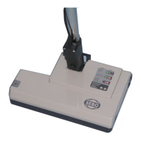
4. Inbetriebnahme
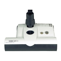
Stecken Sie den Schlauchstutzen
(8) in den Sauganschluss (21) bis er
ein rastet. Schieben Sie eine SEBO
Bo dendüse bis zur Rastung* auf das
untere Ende des Edelstahlrohres
(5a/b). Stecken Sie nun den Hand-
griff (6) in die andere Seite des Edel-
stahlrohres (5a/b) ein.
Je nach Modell stecken Sie vorher
das zweiteilige Edelstahl-Steckrohr
zusammen.
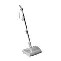
Zur Montage der Anschlussleitung
setzen Sie den Kaltstecker (46) in
die Buchse ein. Führen Sie die An-
schlussleitung anschließend in die
Zugentlastung (47) ein, bis es hör-
bar einrastet. Drücken Sie die An-
schlussleitung nun in die Führungs-
schiene (48) zwischen der Buchse
und der Zugentlastung ein.
* je nach Modell
3. Machine Description
1 SEBO Kombi*
2 Hard floor/carpet Slider*
5a Telescopic Tube*
5b Insertion tube*
6a Hose handle*
6b Hose handle*
7 Hose
8 Hose end
8a Cable strap
9 Catch
10 On/Off knob with
power control
11 LED light
12 Bag full indicator
13 Upholstery Nozzle
14 Crevice Nozzle
16 Parking groove
17 Airbelt bumper
18 Clip
20 Filter bag cover
23 Carrying /Parking groove
32 Filter holder
35 Cable hook
36 Standard Brush*
* Depending on model.
4. Assembly
Push the hose end (8) into the neck
(21). Fit the two-part tube together*.
Push a SEBO floor head onto the
lower end of the tube (5a/b)* until it
locks*. Insert the tube (5a/b)* onto
the hose handle (6/6b) until it locks
into place.
To assemble the mains cable to the
machine, push the rubber plug (46)
of the cable into the socket of the
machine. Once the plug is fully con-
nected to the socket, please insert
the mains cable into the cable cleat
(47). You can hear a „click“ when the
mains cable is fully inserted.
Finally insert the mains cable into
the channel (48) which you will find
between the machine socket and ca-
ble cleat.
* Depending on model.
88a 21