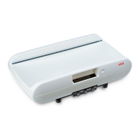
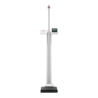
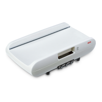
This document describes the seca 727 and 728 high-resolution baby scales with integrated LED display, providing a comprehensive overview of their function, technical specifications, usage, and maintenance features.
Function Description
The seca 727 and 728 scales operate on the principle of signal-dependent pulse-width modulation, utilizing a platform load cell as the force measuring element. Four wire resistance strain gauges are attached to the load cell's surface, forming a bridge circuit. When a load is applied, the spring body deforms, causing a change in resistance that detunes the bridge and produces an output signal. This small analog signal is then directly processed by an A/D converter.
The A/D converter's digital functions are implemented via software in a microcomputer (µC) 520, which serves as the central computing and control element. The µC performs several critical functions including digital A/D conversion, calculation of the zero point, binary BCD segment conversion, display control using multiplex operation, A/D converter testing, CPU and memory testing (RAM and ROM), overload detection, monitoring of the digital supply voltage, automatic zero point monitoring, taring function, and hold function. All these functions are executed through software stored in the µC's programmed memory (ROM).
The scales are designed for both battery and mains operation. A battery charging circuit is included for rechargeable batteries, and a power supply unit detection mechanism adjusts the switch-on time accordingly. Voltage stabilization ensures a controlled 5V or 10V output voltage from a wide input voltage range (6-15V). A reset circuit handles power-on resets and start button presses.
Important Technical Specifications
- Measuring Element: Platform load cell with 4-wire resistance strain gauges.
- A/D Converter Supply: 10V (for seca 717), typically 5V.
- Microcontroller: µC 520.
- Display: 7-segment LED display, controlled via multiplex operation.
- Power Supply: Operates from 6-15V input, regulated to 5V or 10V.
- Battery Charging: Float charge current for extended battery life.
- RS232 Interface: Integrated UART-interface, configurable by software.
- Baudrate: 1200
- Parity: Even
- Databits: 8
- Stopbits: 1
- Startbits: 1
- Handshake: No hardware handshake.
- Data Transmission: ASCII coded bytes, high nibble first, low nibble last. Each block starts with STX and ends with CR, LF, ETX.
- Weighing Ranges (Model 717):
- Range 1: 15kg / 5g
- Range 2: 6kg / 2g
Usage Features
The scales offer several user-friendly features:
- Start-up Sequence: Upon pressing the start button, the µC initiates, performs a self-test (checking RAM cells, CPU commands, and memory value sums), and then determines the zero point. "SECA" is displayed for approximately 1 second during zero point determination.
- Zero Point Follow-up: The scale automatically adjusts the zero point if the current measured value changes only slightly over time.
- Weight Calculation: The weight is calculated by subtracting the zero point value from the current measured value and dividing by the internal step count per displayed step (ne = 10).
- Overload Detection: The scale checks for two limit values:
- Overranging: Displays "STOP" if F = Fmax + 9d (d = graduation).
- Overshooting Limit: Displays "EEEEE" if F = Flim (approx. Fmax + 20%).
- A/D Converter Limit Values: Displays "EEEEE" if the A/D converter's bottom or upper limit is overshot.
- Range Switch-over (Model 717): A dedicated button allows switching between two weighing ranges.
- Hold and Tare Function (Model 727): A single button provides both hold and tare functionalities.
- Tare Range: Up to 0.4 kg.
- Hold Range: From 0.4 kg.
- Taring Function (Models 737 and 757): Activated by pressing the tare button. The tare indicator 27 on the display board illuminates, and the weight on the scale is tared off.
- Hold Function (Models 717, 737, 748, and 757): Activated by pressing the hold button. The weight is retained on the display once it stabilizes, until the hold function is activated again.
- Supply Voltage Monitoring: A monitoring circuit detects low operating voltage, displaying "bAtt" if the voltage is too low. If operating on rechargeable batteries, the electronics switch off after a few seconds to prevent exhaustive discharge.
- Incubator Scale 748 Specifics: Requires relief by at least 0.5 kg for zero point determination, followed by a 1-second sound indicating readiness. Also, the A/D converter circuit is on a separate board for electromagnetic compatibility, with interference-suppression capacitors.
Maintenance Features
The manual provides detailed troubleshooting and replacement instructions for various faults:
- Rechargeable Battery Not Correctly Charged:
- Check battery charging current with an ammeter.
- Verify polarity of diode 106.
- Calibrate charging current using resistor 103.
- Check and replace transistor 104 if no charging current flows.
- Scale Cannot Be Started:
- Battery Operation: Measure rechargeable battery voltage and recharge if necessary.
- Plug-in Power Supply: Check voltage at Z-diode 102 and for short-circuits.
- Check 5V supply voltage at capacitor 518 (4.7V - 5.3V).
- Measure voltage at pin 6 of IC 131; replace diode 110/111 if lower than 6V.
- Check pin 8 of IC 131 and pin 8 of IC 126 for a positive pulse after pressing the start button; replace IC 126 or check diodes 115/118.
- Measure voltage at pin 1 of IC 131 (approx. 5V); check/replace diode 132 or IC 131.
- Check reset circuit at pin 13 of IC 126 for a positive pulse.
- Check pin 9 of IC 520 for a positive pulse; replace transistor 128 or microprocessor IC 520.
- Check microprocessor oscillator frequency at pins 18 and 19 of IC 520 (must be 12 MHz); replace quartz if incorrect.
- If all else fails, replace the microprocessor.
- Scale Displays "bAtt" After Starting:
- Plug-in Power Supply: Check voltage at Z-diode 102 for short-circuits.
- Rechargeable Batteries: Check voltage at capacitor 120 (seca 748: approx. 9V; seca 727/757: approx. 7.2V); recharge or replace battery if different.
- Digit Defective:
- Check driver transistors (201-205) for square-wave signals at base (0.7V amplitude, +4V offset) and collector (5V amplitude). Replace transistor if signals are incorrect.
- Segment Defective:
- Check segment actuation with an oscilloscope.
- Check output of IC 419 and microprocessor IC 520 for segment actuation signal; replace IC 419 or microprocessor if output doesn't switch.
- Mains Operation Monitor Not Working Correctly:
- Scale should switch off after 10 minutes (mains) or 1-2 minutes (battery).
- Check transistor 109 collector voltage (0.2V for power supply unit, 0.2V for rechargeable batteries, 0.65V at base for power supply unit). Replace transistor 109 if incorrect.
- Verify correct components for LED 106 and resistors 107, 108.
- Signal Transmitter (Model 748) Not Working:
- Check microprocessor output (IC 520, pin 34) for 5V with 5kg load, 0V with 1kg relief. Replace resistor network 519 or IC 520 if incorrect.
- Check transistor 324 collector voltage (0.2V with 5kg load, 5V with 1kg relief). Replace transistor 324 if incorrect.
- Check transistor 325 collector voltage (12V or 9V with 5kg load, 0.2V with 1kg relief). Replace transistor 325 if incorrect.
- If issues persist, replace the signal transmitter.
- Scale Does Not Display Correct Weight:
- Check and adjust slope and zero point according to manual adjustment instructions (specific numbers provided for different models).
- Scale Displays "EEEE" After Starting:
- Check and replace fuse 450 or soldering jumper 450.
- Check load cell connections on the main board.
- Fault on Load Cell and Electronics:
- Requires replacement of the load cell, bottom plate, and platform support.
- Supplementary AD Converter Board (Model 748):
- If replaced, the scale must be recalibrated. Apply Sylgard 170 A&B to seal the board.
The manual also includes detailed instructions for opening and assembling the scale, as well as calibration procedures for models 727 and 728, which involve adjusting rotary potentiometers (INCLIN.COARSE and INCLIN.FINE) with a test weight to match the rated display value. A comprehensive spare parts list is provided with item numbers, descriptions, and price stages for various components, including frames, feet, battery compartments, cable harnesses, main boards, platform supports, display boards, baby trays, and load cells.