Do you have a question about the Seca 717A and is the answer not in the manual?
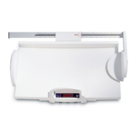
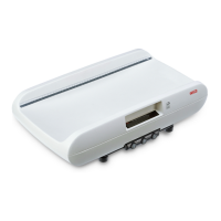
This document provides a comprehensive service manual for the seca 717A, 717 Japan, and 757 baby scales, which are high-resolution, approved baby scales featuring an integrated LED display.
The seca 717A, 717 Japan, and 757 scales operate on the principle of a platform load cell as the force measuring element. Four-wire resistance strain gauges are strategically attached to the load cell's surface and connected in a bridge circuit. When a load is applied, the spring body deforms, causing two resistors in a half-bridge to extend and compress. This deformation alters their resistance, detuning the bridge and generating a change in the output signal, which is proportional to the applied force. For enhanced signal yield, the measuring element and the A/D converter in the seca 717 are supplied with 10V, differing from the usual 5V supply.
The analog-to-digital (A/D) converter directly processes the small output signal from the strain gauge sensor using signal-dependent pulse-width modulation. All digital functions of the A/D converter are implemented via software within a microcomputer. The A/D converter's reference potential is approximately U/2, with the positive input of integrator 402 connected to a bridge output via resistor 506. During a predefined total time, the input voltage +Ue is first connected to integrator 402, followed by the reference voltage U/2 with an FET switch, resistors, and other components. The integrator integrates until comparator 502 reacts, its threshold determined by resistors 410 and 411. Resistor 413 provides positive feedback to prevent comparator oscillation. The microcomputer detects the comparator's trigger and switches off the FET switch, allowing the integrator to run down until the total time has expired. The interval between the start of the integration and the comparator's reaction measures the input voltage Ue.
Temperature compensation for the strain gauge sensor is achieved by connecting a fixed-value resistor in parallel with a temperature-dependent resistor. An NTC combination (511, 512) compensates for the sensitivity's temperature coefficient (t.c.) value, while a PTC combination (405, 406) compensates for the positive t.c. value of the test value. Zero point, sensitivity, and test value are interdependent. The modules (electronics + sensor) are measured at 10°C and 40°C to determine these values, which are then input into a computer. The computer calculates the optimum temperature compensation using a complex routine.
The central computing and control element is the microcontroller (µC) 520, which performs several key functions:
All these functions are implemented via software in the µC's programmed memory (ROM).
Power Supply: The circuit ensures reliable function over a wide input voltage range (6 – 15 V) with a controlled output voltage of 5V or 10V, and low power loss. For the seca 717, an in-phase regulator (451) supplies 10V to the A/D converter and the force measuring element, supported by buffer capacitors (452, 453).
Battery Charging Circuit: Rechargeable batteries are charged via a stabilized power supply (103, 104, 106, 107, 108) and diode 105. The charging current corresponds to the float charge current of the batteries, which is relatively low, extending battery service life. Diode 110 protects the batteries from unlimited current from the power supply unit.
Microprocessor Oscillator: The frequency measured at pins 18 and 19 of the microprocessor (IC 520) must be 12 MHz.
Display: The current weight (F) is shown on a 7-segment LED display, controlled via multiplex operation. Actuation faults affect all segments and are immediately detected. The µC outputs processed 7-segment information to the segment port. Darlington driver 419 and resistor network 317 set the cathodes of the LEDs to 0 V, while shared anodes are connected to +5V via the relevant digit transistor.
Starting the Scale: When the start button is pressed, the µC initiates with reset logics, and the program executes. A self-test is performed, checking RAM cells, CPU commands, and the sum of digits of important memory values. If a fault is detected, "EEEEE" is displayed.
Zero Point Determination: After starting, "SECA" is displayed for approximately 1 second, during which the zero point (Mo) is determined, saved, and subtracted from subsequent measured values. For incubator scale 748, "-UP-" flashes, requiring the scale to be relieved by at least 0.5 kg before a sound signals readiness.
Zero Point Follow-up: If the current measured value (Mi) changes only slightly relative to the zero point (Mo) within a given time (C = 0.5 d/sec), Mi is considered the zero point.
Weight Calculation: Weight is calculated as (Mi – Mo) / ne, where ne is the internal step count per displayed step (ne = 10).
Overload Detection: The current measured value (Mi) is checked against two limits:
Range Switch-over (Model 717): Pressing the weighing range switch-over button (normally the tare button) switches the scale between:
Hold and Tare Function (Model 727): The Hold/Tare button has two functions: Tare range up to 0.4 kg, and Hold range from 0.4 kg.
Taring Function (Models 737 and 757): Activated by pressing the tare button. The µC detects activation, switches on tare indicator 27, and tares off the weight on the scale. The zero point (Mo) is subtracted from the measured value (Mi), and the result is saved as Mt. The weight then results from (Mi - Mo - Mt) / ne. Zero follow-up and overload detection continue, but the measuring range is overshot if F = Fmax + 1d - Mt/ne. If Mi is smaller than Mo by Mt, taring is cancelled, Mt is added back to the zero point, and tare indicator 27 is switched off.
Hold Function (Models 717, 737, 748, and 757): Activated by pressing the hold button. The weight is retained on display once stabilized, until the hold function is activated again.
Switch-on Time: Determined by software as standard. Continuous operation can be achieved by soldering in jumper 618. If a power supply unit is connected, transistor 109 switches through, setting pin 33 of the micro-controller to 0V and extending the switch-on time.
Troubleshooting: A visual inspection is recommended first, checking soldering points, corrosion, soiling, and correct component fitting.
Rechargeable Battery Not Correctly Charged:
Scale Cannot Be Started:
Scale Displays "bAtt" After Starting:
Digit Defective: Check driver transistor (201-205). Base should have square-wave signal (approx. 0.7 V amplitude, +4 V offset). Collector should have square-wave signal (approx. 5 V amplitude). If not, replace transistor.
Segment Defective: Check segment actuation with oscilloscope. Check output of IC 419 by measuring segment actuation signal. If output doesn't switch, replace IC 419. Check output of microprocessor IC 520 or input of IC 419.
Mains Operation Monitor Not Working Correctly:
Signal Transmitter on Model 748 Not Working:
Scale Does Not Display Correct Weight: Check and adjust slope if necessary (refer to manual adjustment instructions: seca 727: 30-34-00-448; seca 737/757: 30-34-00-484; seca 748: 30-34-00-446).
Scale Displays "EEEE" After Starting: Check fuse 450 or soldering jumper 450 and replace if necessary. Check load cell connections on main board. Check and adjust zeropoint if necessary (refer to manual adjustment instructions: seca 727/728: 30-34-00-448; seca 717/737/757: 30-34-00-484).
Model 748 Specific Checks: Check cables between main board and supplementary board (soldered connections, signals 5V, GND, REF, TEST on supplementary board, COM signal on main board). If no signal, replace cable. Refer to oscillograms for signal checks (pulse widths of REF and COM vary with load). Check force sensor connections (for seca 748, drawing 08-06-04-541). If all cables are okay, fault is in AD converter or microprocessor. If supplementary AD converter board on model 748 is replaced, scale must be calibrated (instructions 30-34-00-446 and 30-34-00-487). Apply Sylgard 170 A&B to seal supplementary board. The scale must be recalibrated.
Replacement Instructions:
Adjustment Procedure (Model 717, also suitable for 757):
| Capacity | 200 kg |
|---|---|
| Graduation | 100 g |
| Power Supply | Batteries |
| Functions | Weight measurement |
| Display | LCD |