Do you have a question about the Seca 703 CN and is the answer not in the manual?
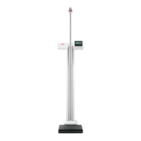
Provides an overall view of the seca 703/704 scale, illustrating key components.
Introduces the DMS modules, their purpose, and configuration via EEPROM and SeSAM bus.
Explains how DMS modules measure weight using load cells and a third-order polynomial.
Details the LCD display capabilities, characters, and units used in the scale.
Explains the process of compensating for load cell temperature drift using capacitor charging.
Describes power sources (batteries, mains) and voltage regulation for digital and analog parts.
Covers button functions, calibration mode activation, and vibration sensor input.
Details EEPROM usage for parameters, program sequence, coefficients, and data storage.
Explains the SeSAM bus for calibration, module connection, data transfer, and switching.
Describes how the SeSAM bus initiates fault messages and lists common fault codes.
Explains the 4.19MHz quartz time base controlling scale processes like timeouts and on-time.
Details the recalibration function to compensate for linear measuring errors and geographical gravity differences.
Explains functions like Tare, Hold, Autohold, and Replace weight implemented via EEPROM.
Outlines requirements for EEPROM data, polynomial calibration, and temperature compensation measurements.
Specifies supply voltage range and current consumption for the scale.
Defines the acceptable operating and storage temperature ranges for the scale.
Introduces display modules, their role in showing weight and processing operating elements via SeSAM bus.
Describes the LCD display update rate, digit capacity, and special characters.
Explains power supply from SeSAM bus for display modules.
Covers button configuration and entry into verification/recalibration modes.
Details the SeSAM bus function for connecting display modules and data exchange.
Explains assigning ID codes via soldering jumpers for module addressing.
Describes optional LCD backlighting for display modules.
Mentions optional signal transmitters using piezo diaphragms.
Details optional clock functions and time display on modules.
Describes fault messages initiated by SeSAM bus and lists specific fault codes.
Explains the recalibration function for linear errors and gravity differences.
Details functions like Tare, Hold, Autohold, and Replace weight implemented via EEPROM.
Describes menu functions like BMI calculation, ideal weight deviation, and limit weight signals.
Specifies supply voltage range, current consumption, and backlighting current.
Defines operating and storage temperature limits for display modules.
Lists dimensions for different display types (small, large, backlit).
Illustrates the cabling for seca 703/704 models, showing connections between modules.
Depicts the cabling for the seca 703 model, detailing component connections.
Lists possible causes like battery issues or defective voltage supply and their remedies.
Covers causes like transport safeguard, maladjustment, or sensor damage and remedies.
Addresses issues like short circuits or defective displays and their solutions.
Details errors related to display or sensor issues and their respective checks.
Explains specific error codes like Er:x:10 related to sensor issues and recalibration.
Lists errors like Er:x:11, Er:x:12, Er:x:14, Er:x:15, Er:x:21, Er:x:22 and their causes/remedies.
Covers faults like Er:x:32, Er:x:40, Er:x:41, Er:x:50, Er:x:51 and their remedies.
Explains that scales use software-controlled calibration via existing controls without external tools.
Details the calibration counter that tracks recalibration procedures and aids verification.
Describes the initial steps to switch scales to calibration mode using button presses.
Details the process of adjusting weight values using kg/lbs key and potential error codes.
Explains timeout controls in calibration mode and requirements for test weights to avoid errors.
Provides a step-by-step example of recalibrating a scale with a 100 kg test weight.
Summarizes user key presses and corresponding system responses during recalibration.
Outlines safety precautions and initial steps for opening the scale for replacement.
Details steps for detaching connections, removing screws, and replacing the DMS module.
Provides instructions for unsolder connections, removing screws, and replacing the load cell.
Explains replacing the cable harness, requiring column removal and specific screw removal.
Details steps for unscrewing covers, detaching connections, and replacing display, keyboard, and battery parts.
Guides on reassembling the scale in reverse order and performing necessary adjustments.
Shows Picture 1 of the scale's internal components relevant to replacement.
Shows Picture 2 illustrating the load cell assembly for replacement.
Provides an exploded view of the display unit and related parts for replacement.
Lists part numbers and designations for display housing, profiles, and operating housings.
Details part numbers for membrane keyboards, stickers, and board holders for the display.
Lists part numbers for DMS display electronic modules and battery compartment parts.
Lists calibration count stickers and power supply units.
Shows an exploded view of display parts with corresponding item numbers for identification.
Lists part numbers and designations for load cells, cross beams, and connection components.
Details parts for the frame, bubble level, plugs, platforms, and mats.
Lists rollers, covers for DMS modules, and fixing bolts.
Lists various folding box options for different scale models.
Shows an exploded view of baseframe parts with item numbers for identification.
Lists parts for the DMS high end baseframe including frames, rollers, and connectors.
Details parts like load cells, cross beams, and platforms for the DMS high end model.
Lists mains connection harnesses, plugs, and mats for the DMS high end baseframe.
Lists folding box options for the DMS high end model.
Provides an exploded view of DMS high end baseframe parts with item numbers.