Housing grounding
place
Washer
Bolt
Washer
Nut
Nut
Protective Earth
wire PE
Analog PSTN line
Washer
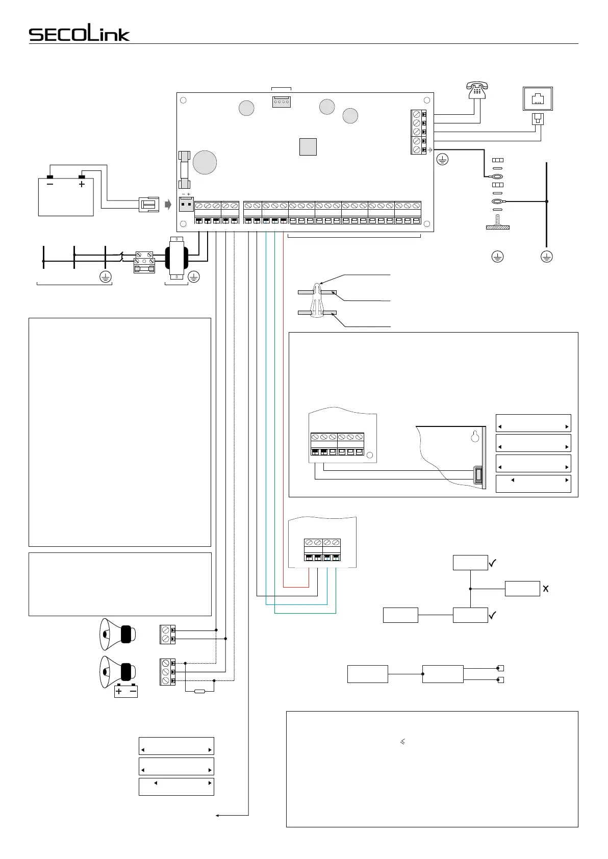
One 12V 7Ah rechargeable battery is
necessary for correct Control Panel
PAS8xx operation. The battery is used
as back-up power supply in case of the
AC power supply loss.
The battery is used as extra power
supply in case of a temporary load
increase (the siren or the radio
transmitter is ON).
Power supply
distribution board
AC power transformer:
Primary winding: 230V AC 50Hz
Secondary winding: 20V AC 50Hz
~
~
12V battery
7Ah/20HR
Black
Red
Serial port SERIAL (see "Module wiring")
Wiring diagrams
10kW
Siren without battery
Siren wirh battery
+12V
COM
S
+12V
COM
If a high level is not enough for siren control, it is necessary to
connect a 3-15 kOhm resistor between terminals +BELL and -PGM.
Note: In the template output
+BELL is set for wiring the
siren without a battery. If you
wish to wire a siren with a
battery it is necessary to
change the +BELL (00_1
PGM) definition to "Power
supply" setting.
Zones (see "Zone wiring")
X1
BAT
3.15A
PAS808
PAS808M
PAS808R
PAS816
PAS832
Live
wire
L
Neutral
wire
N
Protective
Earth wire
PE
Fuse
250mA
Secolink security systems are supplied to
customers with a pre-installed template in the
keypad memory. The template data has been
transferred to registered system modules during a
system start up ("First start"). The template
includes 1 partition and 8 zones. Zone Z1 is used
for wiring of the magnetic door contact that
monitors the opening/closing of the door. Zone Z2
is intended for an entry/exit path motion sensor
wiring, zones Z3, Z4 are used for wiring of interior
motion sensors, zone Z5 is intended for smoke
detector wiring (the smoke detector must be
powered from the PGM output +PGM). Zone Z6 is
used for tamper switch wiring. Turn OFF the
tamper monitoring if you wish to use zone Z6 for
other purposes. In the template the keypad zones
corresponds to the first zones of control panel on
operation. The programable outputs:
+BELL is used for wiring a siren without battery
(00_1 PGM);
-PGM – for control a siren with battery (00_2 PGM);
+PGM is used for smoke detector powering (00_3
PGM).
Template
Setting:
Default PIN codes
Default service PIN 0000
Default user 01 PIN 0001
Default user 02 PIN 0002
...
Default user 31 PIN 0031
System Setup:
Definition
PGM Outputs
Power Supply
O01
Note: In the template output +PGM (00_3 PGM) is
set for the smoke detector powering (see page
5 "Wiring samples").
AC1 AC2 +BELL COM -PGM +PGM COM CLK DAT +AUX Z1 COM Z2 +AUX Z3 COM Z4 +AUX Z5 COM Z6 +AUX Z7 COM Z8
TIP
RING
T-1
R-1
DAT
+AUX
Z1
COM
Z2
+AUX
Z3
Z4
+AUX
Z5
COM
Z6
+AUX
Z7
COM
Z8
CLK
COM
-PGM
COM
+BELL
+PGM
AC2
AC1
Maximum permissible long term load of the power supply:
Maximum permissible load of the +AUX output (switching "+"):
Maximum permissible battery charging current:
0,7 A
+0,8 A
0,4 A
Operational maximum ratings of control panel PAS8xx
Maximum permissible load of the +BELL output (switching "+"):
Maximum permissible load of the -PGM output (switching "-"):
Maximum permissible load of the +PGM output (switching "+"):
+0,8 A
-0,05 A
+0,8 A
Battery is disconnected when voltage is less than: 9,5 V
(I + I + I 0,7 A )
+AUX
+BELL +PGM
R-1
T-1
RING
TIP
COM
+BELL
COM
+BELL
COM
-PGM
+PGM
DAT
+12V CLKCOM DAT
COM
DAT
+12V
CLK
CLK
COM
+AUX
Module
PAS8xx board
Plastic stud
Cabinet wall
Control panel and modules have to be fastened in
the Alarm System housing (CAS8, CAS8M) using
plastic studs. The module mounting holes should
correspond to housing rear wall apertures. Do not
forget to fix the plastic studs in the apertures before
fastening the housing on a wall.
Z6
AUX
Z7
COM
Z8
Note: The data line (CLK, DAT) length (the distance between
control panel and module) must not exceed 300 metres. It is
recommended to use a 6-wire or 8-wire cable for the module
wiring. It is advised to use the free wire pairs for the module
power supply, when the modules are on considerable
distance from PAS8xx.
Service Mode:
System setup
System setup:
Modules:
Use Tamper
Settings
No
M00
Turning OFF the Tamper:
Housing tamper
switch
Tamper function
PAS8xx
Module
A
B
C
Voltage is measured only in a point A. The voltages on terminals of connected
detectors B, C should be measured using a voltmeter.
It is possible to find out the voltage between module terminals +12V ir COM during
the voltage test ("Main Menu/Test/Voltage Test"). The SECOLink module supply
voltage should be in the range of 9-14 V, but for module RCM800(wl) it should
exceed 10,5 V if the Relay PGMs are used.
COM Z6 +AUX Z7 COM Z8
COM
CAS8, CAS8M
PAS8xx
PAS8xx Module 1
Module 2
75 m
Module 3
150 m
75 m
(375 m)
(300 m)
(150 m)
150 m
Modules
Short wiring manual – basic information
Control Panels PAS8xxControl Panels PAS8xx
Intruder alarm system
Service Mode:
System Setup
Note: In the template PAS8xx zone Z6 is used for wiring the tamper switch of the
housing. If the housing door is opened the system will indicate a trouble or will
raise an alarm if the system is armed. If the Tamper function is not necessary it is
possible to turn it OFF and use Z6 as a normal zone.
9,5 V
Page 2
 Loading...