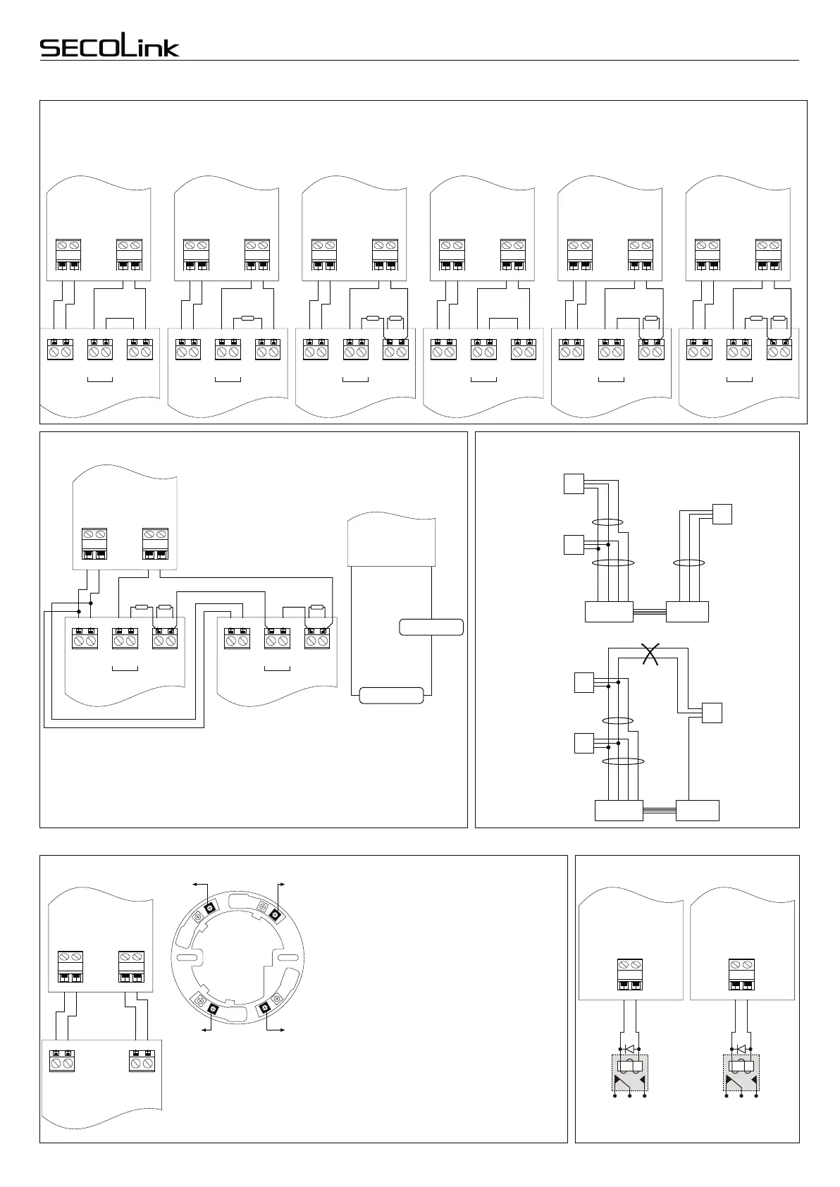
Wiring of zones
Normally closed
contact
(NC)
+12V +12V
COM COM
NC NOT2 T2COM COMT1 T1
Sensor
Normally closed
contact with one
resistor
(NC/EOL)
+12V +12V
COM COM
Normally closed
contact with two
resistors
(NC/DEOL)
+12V +12V
COM COM
Normally open
contact
(NO)
Normally open contact
with one resistor
(NO/EOL)
Normally open contact
with two resistors
(NO/DEOL)
NCT2 COMT1
1kW
NC NOCOM COMT2 T2T1 T1
1kW 1kW1kW 1kW1kW
NOCOMT2T1
Wiring of single zones
Wiring of double zones (only PAS832)
+AUX COM Z1 COM
+AUX
COM
Z1
COM
+AUX COM Z1 COM
PAS8xx or module PAS8xx or module PAS8xx or module PAS8xx or module PAS8xx or module PAS8xx or module
+AUX
COM
Z1
COM
+AUX COM Z1 COM
+AUX
COM
Z1
COM
+AUX COM Z1 COM
+AUX
COM
Z1
COM
+AUX COM Z1 COM
+AUX
COM
Z1
COM
+AUX COM Z1 COM
+AUX
COM
Z1
COM
+12V
COM
T1
T2
COM
NC
+12V
COM
T1
T2
COM
NC
+12V
COM
T1
T2
COM
NC
+12V
COM
T1
T2
COM
NO
+12V
COM
T1
T2
COM
NO
+12V
COM
T1
T2
COM
NO
Tamper TamperTamper Tamper Tamper Tamper
Z2
PAS8xx
+AUX
COM
Z2
Sensor
Sensor
Z1
Cable
Cable
+AUX
COM
Sensor
+AUX
COM
Z1
Cable
EXM800
+AUX
COM
Z1
Z2
PAS8xx
+AUX
COM
Z2
Sensor
Sensor
Z1
Cable
Cable
+AUX
COM
Sensor
EXM800
ATTENTION! Sensors must be wired without loops
1kW 620W
PAS832
+AUX
COM
Z1
COM
NC*COM
Sensor A
+12V
COM
T1
T2
COM
NC*
Tamper
NC*COM
Sensor B
+12V
COM
T1
T2
COM
NC*
Tamper
300W
+12V
COM
T2T1 T2T1+12V
COM
+AUX COM Z1 COM
Sensor A
Sensor B
* - Sensor contact type may be NC or NO.
PAS832
Correct sensor wiring
Wrong sensor wiring
Sensor Sensor Sensor Sensor Sensor
Wiring samples
Wiring of 4-wire smoke detector
+12V
COM
NOCOM
Detector
+PGM COM Z5 COM
PAS8xx
+PGM
COM
Z5
COM
+12V
COM
COM
NO
Note: the smoke detectors made by
different manufacturers may have a
different contact layout. For more
detailed information about contact
layout look the documentation
supplied by manufacturer of smoke
detector.
The contacts of smoke detector
3
4
2
6
5
To COM
To zone
To COM
To +PGM
D1
NCNC
NONO
Relay
PAS8xx or module
+PGM COM
+PGM
COM
D1
NCNC
NONO
Relay
PAS8xx or module
+AUX -PGM
+AUX
-PGM
For relay wiring it is recommended to use the
protective diode which would limit the induced
current appearing during turning OFF the relay.
Wiring of relays
The smoke detectors may be triggered by dust, so in
order to prevent false alarms it is necessary to
execute an trigger re-check. For achievement of this
objective an attribute “Fire verification” has to be
assigned to the system’s fire zone, the smoke
detector has to be powered by PGM output with
definition “Fire Power Supply”and the fire zone has to
be assigned to the corresponding PGM trigger
source. In the template is set that fire zone is the
control panel zone Z5, the +PGM2 output is used for
power supply of smoke detectors.
Operation: In order to check the triggered smoke
detector it’s power supply has to be turned OFF and
turned ON again. The system turns OFF the PGM
output for a time equal to PGM trigger time. When this
time expires the system turns ON the PGM output
again and waits for detector operating status settling
(”Detector settling time”). The system executes the
detector trigger re-check with duration equal to “Fire
verification time”. If during this time the smoke
detector is triggered again the system raises a fire
alarm and sends report, if there are no smoke detector
trigger the system does not alarm.
Page 5
Short wiring manual – basic information
Control Panels PAS8xxControl Panels PAS8xx
Intruder alarm system
 Loading...