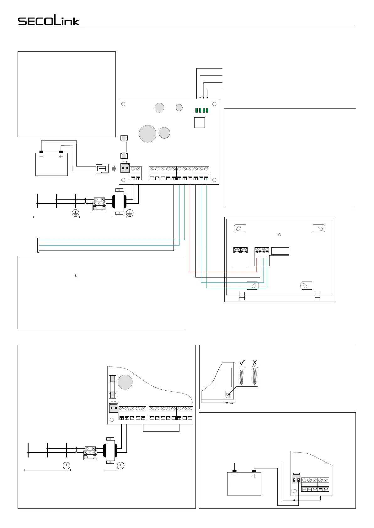
Wiring of modules in large or high security level systems
Power supply
distribution board
AC power transformer:
Primary winding: 230V AC 50Hz
Secondary winding: 20V AC 50Hz
~
~
12V battery
7Ah/20HR
Black
Red
Live
wire
L
Neutral
wire
N
Protective
Earth wire
PE
Fuse
250mA
X1
BAT
OVL
CHG
LOW
MOD
PWR15
PWR20
MOD - indicates a module address in system.
LOW - indicates low module battery status.
CHG - indicates battery charging status.
OVL - indicates an overload of +BELL or + AUX.
KRbus
PWR20 – additional power supply with bus
repeater and three PGMs
Disconnect the system from 230V AC
power supply, pull out the battery cable
plug from the BAT socket. Make a short
circuit between the PGM output and
zone Z1 (see diagram) using a wire.
Power up the system with battery is
unpluged. As these actions has been
done it is possible to enter the service
mode using restored default service
PIN = “0000".
Default service PIN restoring
System start-up with no AC 230V power
X1
BAT
3.15A
+BELL
COM
CLK-I
DAT-I
+AUX
COM CLK-O
DAT-O
-PGM1-PGM2
-TMPR
AC ~ AC
Power supply distribution board
AC power transformer:
Primary winding: 230V AC 50Hz
Secondary winding: 20V AC 50H
~
~
Live
wire
L
Neutral
wire
N
Protective
Earth wire
PE
Fuse
250mA
AC1 AC2 +BELL COM -PGM +PGM COM CLK DAT +AUX Z1 COM Z2
AC
AC
-PGM1
-PGM2
-TMPR
+BELL
COM
CLK-I
DAT-I
+AUX
COM
CLK-O
DAT-O
AC1
AC2
+BELL
COM
-PGM
+PGM
COM
CLK
DAT
+AUX
Z1
COM
Z2
DAT from PAS8xx
CLK from PAS8xx
COM from PAS8xx
3.15A
X1
BAT
AC1 AC2 +BELL COM -PGM
AC1
AC2
+BELL
COM
-PGM
12V battery
7Ah/20HR
Black
Red
Maximum permissible long term load of the power supply:
Maximum permissible load of the +AUX output (switching "+"):
Maximum permissible battery charging current:
1 A
+1 A
0,4 A
Operational maximum ratings of PWR15
Maximum permissible load of the +BELL output (switching "+"):
Maximum permissible load of the -PGM1 output (switching "+"):
Maximum permissible load of the -PGM2 output (switching "+"):
+2 A
-0,05 A
-0,05 A
Battery is disconnected when voltage is less than:
9,5 V
(I + I 1 A )
+AUX
+BELL
Wire
KM20B, KM20BT
Z2
COM
+12V
Z1
+12V
COM
CLK
DAT
DAT
CLK
COM
+AUX
CLK
DAT
+12V
COM
+12V
Z1
Z2
COM
Additional information
Keypad attachment
Keypad
Safe wiring of outdoor siren
Page 4
Short wiring manual – basic information
Control Panels PAS8xxControl Panels PAS8xx
Intruder alarm system
Modules PWR15, PWR20 are powered
by a separate power transformer, a
separate rechargeable 12V 7Ah battery
should be wired. If alarm system includes
PWR15, PWR20 it is recommended to wire
an outdoor siren to the PWR15, PWR20
terminals +BELL, -PGM1 (-PGM2) and
COM by the way as it is shown on page 2.
Thus at trouble of the battery of an outdoor
siren or short circuit in the power wires of an
outdoor siren the increased current will
have no influence on the control panel
operation.
The repetition of bus is a perfect solution when the criminals
are trying to neutralize the security system by shorting the
keypad wiring located near an entry door or the PROX8
wiring with a hope it will disturb the operation of the system.
In this case only the modules wired to the bus repeated by
PWR20 would stop operate, but the remaining part of the
system would operate, would send a burglary alarm report
and would cause additional difficulties to the intruders.
The terminals CLK, DAT and COM of the control panel
PAS8xx are wired to the terminals CLK-I, DAT-I and COM
of the module PWR20. Re-transmitted bus appears on the
CLK-O and DAT-O terminals. Modules that use the re-
transmitted BUS are powered by PWR20 output +AUX.
For the attachment of keypads use only
self-tapping screws with flat (countersunk)
head (3x30 PH). Make sure that the screw
is screwed completely and the head is
sinked into the wall of the housing. If you
are using other type of screws or if you fail
to screw them fully there is a possibility of
the screw touching the keypad electronics
wich would cause the keypad fail.
Connect 12VAh/20HR battery to the PAS8xx BAT connector. With an
additional wire connect the negative battery pole to the PAS8xx COM
terminal for a short time. The system will start operate however the AC
loss trouble will be indicated.
 Loading...