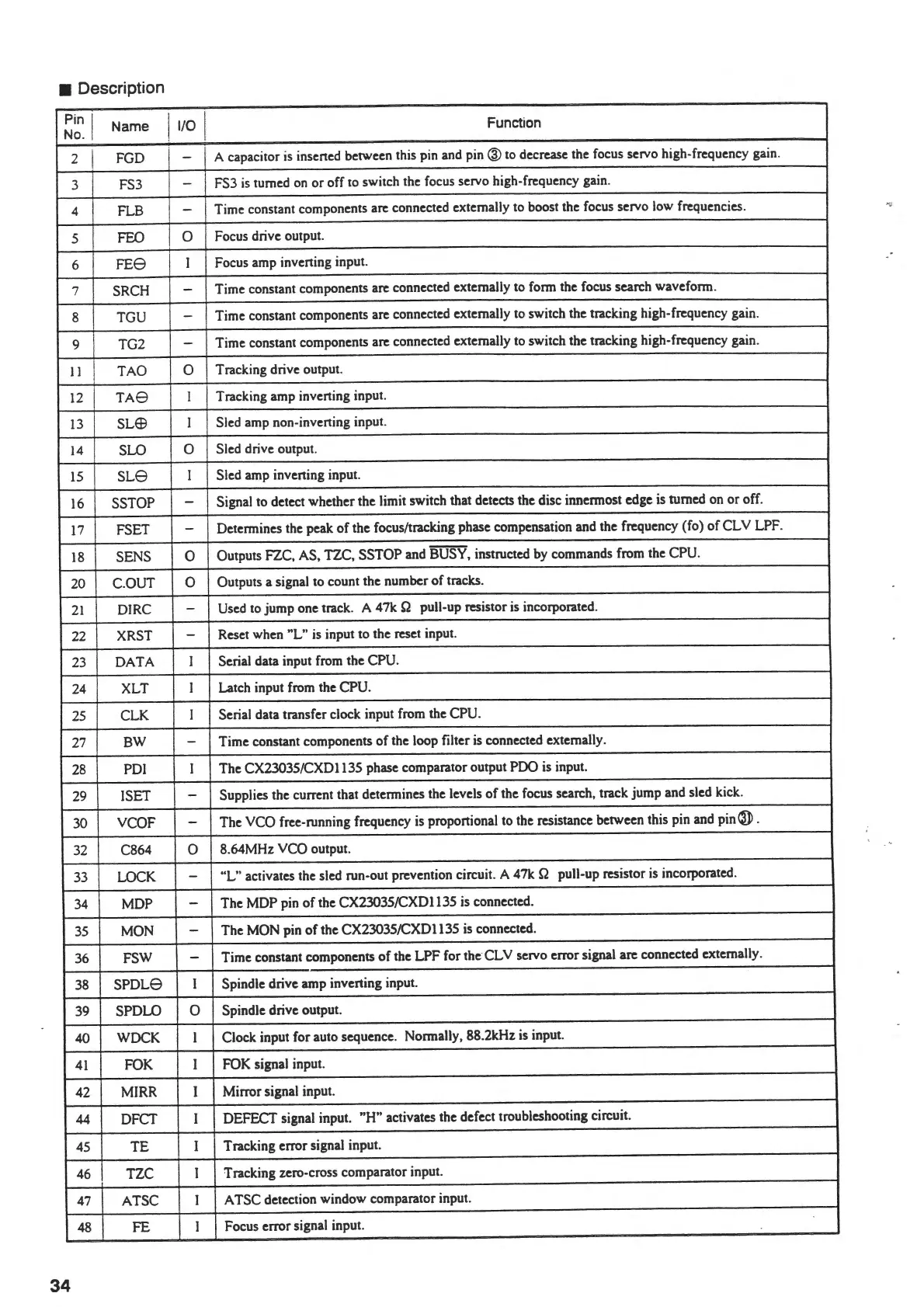
• Description
Pin I
No.
Name
I
1/0
I
Function
2
I
FGD -
A capacitor is insened between this pin and
pin®
to decrease the focus servo high-frequency gain.
3 FS3
- FS3
is
turned on
or
off to switch the focus servo high-frequency gain.
4
FLB
- Time constant components arc connected externally to boost the focus servo low frequencies.
5
FEO
0
Focus drive output.
6
FE8
I
Focus amp invening input.
7
SRCH
-
Time constant components arc connected externally to form the focus search waveform.
8
TGU
-
Time constant components arc connected externally to switch the tracking high-frequency gain.
9 TG2
-
Time constant components arc connected externally to switch the tracking high-frequency gain.
II
TAO
0
Tracking drive output.
12
TA8
I
Tracking amp invening input.
13
SUB
I Sled amp non-invening input.
14
SLO
0
Sled drive output.
15
SL8
I Sled amp inverting input.
16
SSTOP - Signal to detect whether the limit switch that detects the disc innermost edge is turned on
or
off.
17
FSET -
Determines the peak
of
the focus/tracking phase compensation and the frequency (fo)
of
CLY LPF.
18
SENS 0
Outputs FZC, AS, TZC, SSTOP and BUSY, instructed by commands from the CPU.
20
C.OUT
0
Outputs a signal to count the number
of
tracks.
21
DJRC
-
Used to
jump
one track. A
47k
Q pull-up resistor is incorporated.
22 XRST
-
Reset when "L" is input to the reset input.
23
DATA
I Serial data input from the CPU.
24 XLT
I
Latch input from the CPU.
25
CLK
I Serial data transfer clock input from the CPU.
27
BW
-
Time constant components
of
the loop filter is connected externally.
28 PD!
I The CX23035/CXD 1135 phase comparator output PDO is input.
29
!SET
-
Supplies the current that determines the levels
of
the focus search, track jump and sled kick.
30
VCOF - The VCO free-running frequency is proponional to the resistance between this pin and
pin@
.
32 C864
0
8.64MHz VCO output.
33
LOCK
-
"L"
activates the sled run-out prevention circuit. A 47k Q pull-up resistor is incorporated.
34
MDP
-
The MDP pin
of
the CX23035/CXD 1135 is connected.
35
MON
-
The MON pin
of
the CX23035/CXD1135 is connected.
36
FSW
-
Time constant components
of
the
LPF
for the
CL
V servo error signal arc connected externally.
38
SPDL8
I Spindle drive amp inverting input.
39 SPDLO
0
Spindle drive output.
40
WDCK
I Clock input for auto sequence. Normally, 88.2kHz is input.
41
FOK
I
FOK signal input.
42
MIRR I Mirror signal input.
44
DFCT I DEFECT signal input.
"H" activates the defect troubleshooting circuit.
45
TE
I Tracking error signal input.
46
TZC
I
Tracking zero-cross comparator input.
47
ATSC
I
A TSC detection window comparator input.
48
FE I
Focus error signal input.
34