4.
CD DRIVE ADJUSTMENT
6
4-1. Test Equipment and Test Disc
J) Frequency counter
2) Oscilloscope (20MHz
or
more)
3) Adjustment jig (MEGA-CD II (F) CD ADJ. JIG)
4) Audio generator
5) Voltmeter (two units with one needle
or
one unit with two needles)
6) Test CD (SONY TYPE-4)
4-2. Set-up for Adjustment
J) Connect both terminals
of
J40 I.
2) Tum SW401 on and fix
it
using plastic tape, etc.
3) Connect the jig to CN403.
('4)
Supply power to the unit and jig. (Use AC adaptor
of
MEGA
CD
II /SEGA CD II for jig)
\
~)
Press the [RESET] switch
of
the jig so the counter reads
"O"
. .
6) Connect the Q301
's
emitter and CNIOl pin 28 B
or
connect Mega Drive II /Genesis II .
(
Sn,
.
,,vfJ
IJ
f
f51:_lw.;~
rv
) 1..r/
f'
'-t-
Test mode
Adjustment item
0
vco
2
EF
balance
3
Tracking gain
Note 1: The test mode
is
incremented each time the [TEST] switch
of
the jig is pressed.
Note 2: Test mode I
is
for checking the laser power and keeps the pickup laser illuminated.
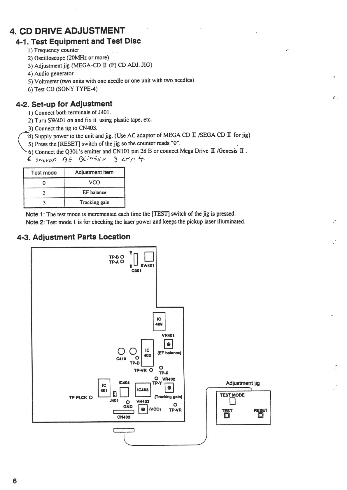
4-3. Adjustment Parts Location
TP·PLCK 0
ED
TP-80
0
TP·A
0
B SW401
0301
0 0
~
1
;2
C410 0
TP-D
TP-VR
0
VR401
[!]
(EF balance)
0
TP-X
r;i
IC404
0 VR402
~mD
J401 0
GND
CN403
BTP-Y~
(Tracking gain)
VR403
[!]
(VCO)
TP°.vR
Adjustment
jig
TEST
MODE
0
TEST
RESET
ICI
ICJI
C .