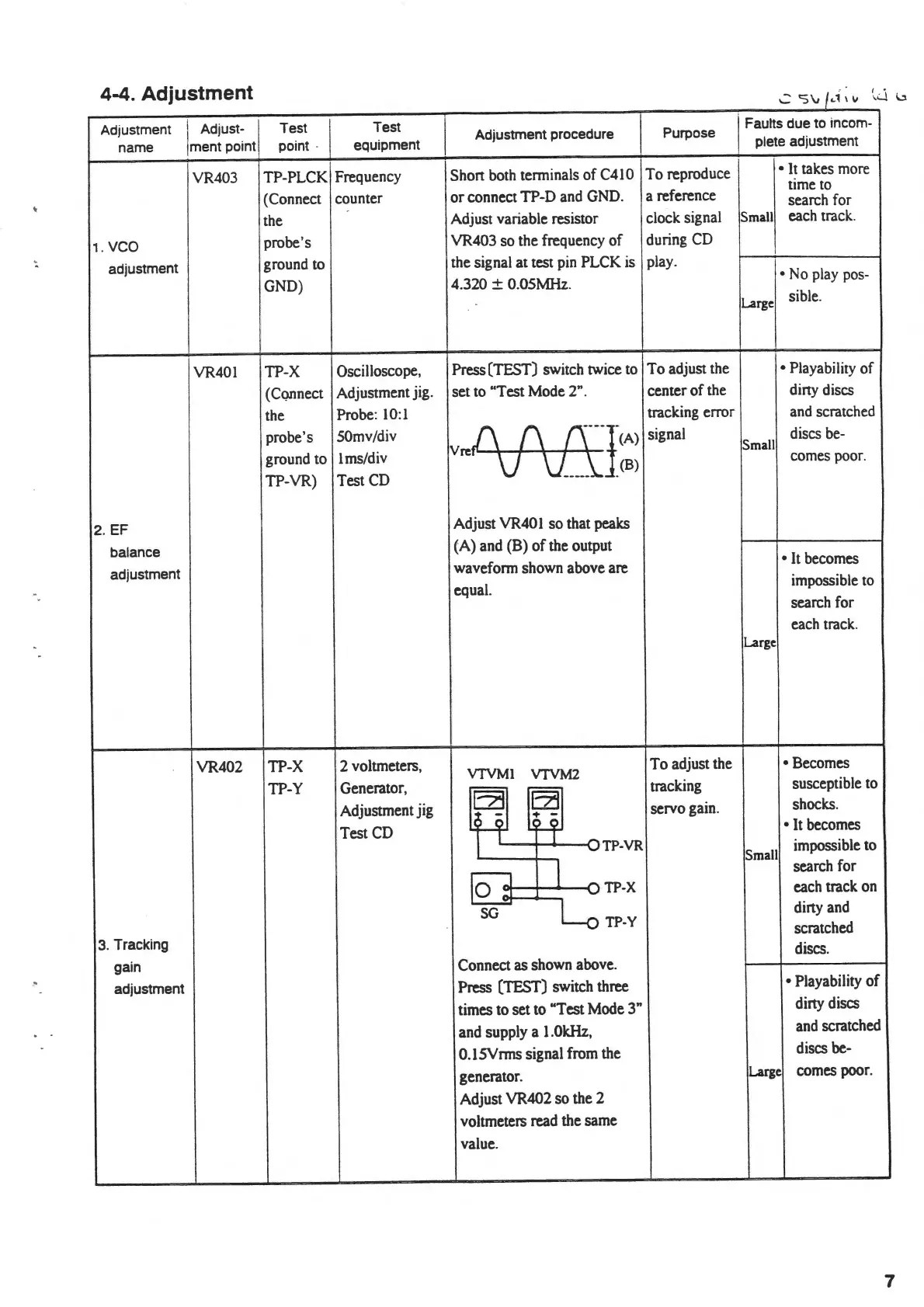
4-4 Adjustment
.
'2'S'v/·.:i111
I •
..,.i
\.:!.
\
Adjustment
I
Adjust-
I
Test
Test
Adjustment procedure Purpose
I Faults due
to
incom-
name
Jment
point
point
·
equipment
plete adjustment
VR403 TP-PLCK
Frequency Shon both terminals of
C410
To
reproduce
•
It
takes
more
time
to
(Connect counter
or
connect TP-D
and
GND.
a reference
search for
the
Adjust variable resistor
clock signal
Small
each track.
1. vco
probe's VR403 so the frequency of during
CD
the signal at test
pin
PLCK is
I
adjustment
ground
to
play.
•No
play
pos-
GND)
4.320 ±
O.OSMHz.
Large
sible.
VR401
TP-X
Oscilloscope, Press (TEST) switch twice
to
To adjust the
• Playability
of
(CQllnect
Adjustment jig. set
to
"Test Mode 2".
center of
the
diny discs
the
Probe:
10
:1
tracking error
and
scratched
probe's 50mv/div
v
..
.O
(\
rcy)
signal
discs
be-
Small
ground to I ms/div
vv=i
_(B)
comes
poor.
TP-VR) Test
CD
2.EF
Adjust VR40 I so that peaks
balance
(A) and (B)
of
the
output
adjustment
waveform shown above are
•It
becomes
equal.
impossible
to
search for
each
track.
Large
VR402
TP-X
2 voltmeters,
VTVMI
VTVM2
To adjust the •Becomes
TP-Y Generator,
EZI
ai
tracking
susceptible to
Adjustment jig servo gain.
shocks.
-
Test
CD
'O
•It
becomes
)
VTP-VR
Small
impossible to
lo3
I
search for
vTP-X
each track
on
-
diny
and
SG
TP-Y
scratched
3.
Tracking
discs.
gain
Connect as shown above.
adjustment
Press (TEST) switch three
• Playability
of
times to set to "Test Mode 3"
diny discs
and supply a l
.OkHz,
and
scratched
O.lSVnns signal from the
discs be-
generator.
Large
comes
poor.
Adjust VR402 so the 2
voltmeters
read
the same
value.
7