IC4 IC Z84C0006
Pans No. : 315-0738-R
IC UPD9033GB-4-384
Pans No. : 315-5676-R
IC TMPZ84COOAU-6
Pans
No.
: 315-0782-R
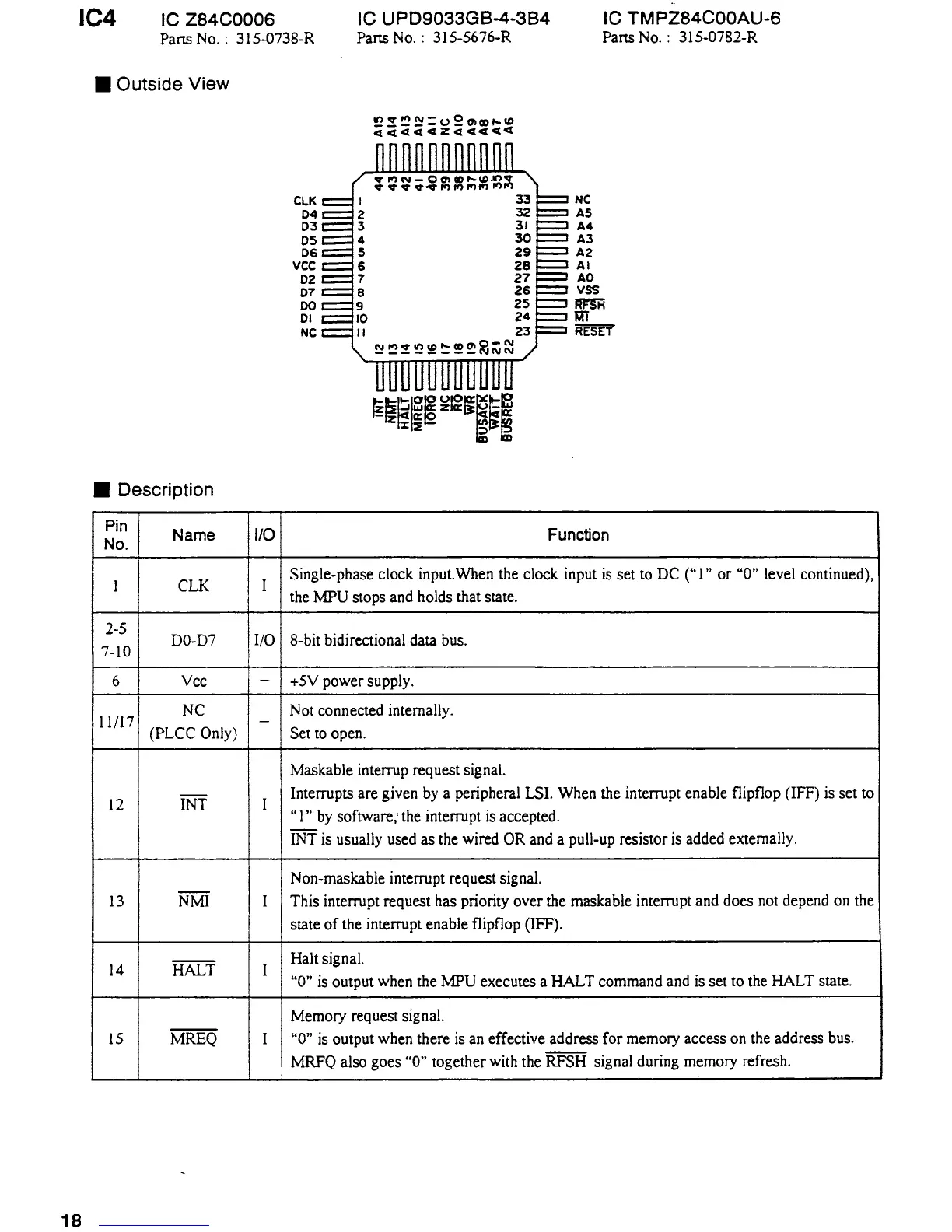
• Outside View
• Description
Pin
I
Name
No.
1 CLK
2-S
7-IO
DO-D7
6
Vee
II/17
NC
(PLCC Only)
I2
INT
I3
NMI
14
HALT
IS MREQ
18
1/0
I
I/0
-
-
I
I
I
I
eLK
04
03
05
06
vee
02
07
DO
01
Ne
;~~;~~:g::;~~~
33
32
31
30
29
28
27
26
25
24
23
NC
AS
A4
A3
A2
AI
AO
vss
~
'fli
RESET
Function
Single-phase clock input. When the clock input is set to DC ("1"
or
"0" level continued),
the
MPU stops and holds that state.
8-bit bidirectional data bus.
+SV power supply.
Not connected internally.
Set to open.
Maskable interrup request signal.
Interrupts are given by a peripheral LSI. When the interrupt enable flipflop (IFF)
is
set
to
"I"
by
software,· the interrupt is accepted.
INTis
usually used as the wired OR and a pull-up resistor is added externally.
Non-maskable interrupt request signal.
This interrupt request has priority over the maskable interrupt and does not depend on the
state
of
the interrupt enable flipflop (IFF).
Halt signal.
"0" is output when the MPU executes a HALT command and is set to the HALT state.
Memory request signal.
"0" is output when there is an effective address for memory access on the address bus.
MRFQ also goes
"0" together with the RFSH signal during memory refresh.

 Loading...