Do you have a question about the Seifert 43301081 and is the answer not in the manual?
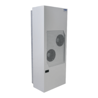
This document describes the Seifert cooling unit, model 43301081, designed for industrial enclosures.
The cooling unit operates on a refrigeration circuit with four main components: compressor, evaporator, condenser, and expansion device. It uses R134a refrigerant, which is chlorine-free with an Ozone Destruction Potential (ODP) of 0 and a Global Warming Potential (GWP) of 1430. The compressor compresses the refrigerant to high pressure and temperature, pushing it through the condenser where it cools and changes from gas to liquid. It then passes through a capillary pipe, reducing pressure before reaching the evaporator. In the evaporator, the refrigerant absorbs heat, changing from liquid to gas, and is then drawn back into the compressor to complete the cycle.
The unit is intended as a complementary accessory to larger industrial equipment, dissipating heat from electrical control cabinets or similar enclosures to protect heat-sensitive components. It is not intended for household use. The unit has two completely separate air circuits, ensuring that the clean cabinet air does not come into contact with dirty or polluted ambient air.
For condensation management, standard cooling units have a drain socket at the bottom for a drain pipe. Units with an internal condensate evaporator (43XXX1XX models) use self-regulating PTC cartridges. Condensate is drained to an internal recipient where it evaporates upon contact with the cartridge surface, with the resulting steam directed towards the condenser. The PTC heater cartridge is permanently connected. An overflow socket is provided at the bottom of the unit, for which a drain pipe is supplied.
The unit is equipped with a temperature controller that regulates the air-conditioning cycle. The display shows the temperature inside the enclosure. The cooling set point (St/St1) is pre-set at 95°F and can be adjusted between 68°F and 122°F. The unit also features a potential-free high-temperature alarm relay (normally closed configuration) pre-set to switch when the enclosure temperature exceeds 131°F.
Order Number: 43301081 Cooling capacity 95F/95F: 10,240 BTU Cooling capacity 95F/122F: 8,260 BTU Compressor type: Rotary piston compressor Refrigerant: R134a, GWP 1430 Refrigerant charge: 900 g / 31.7 oz High / low pressure: 29.5 / 6 bar (428 / 88 psig) Operating temperature range: 50°F – 131°F Air volume flow (system / unimpeded):
Mounting: The unit is designed for recessed mounting. It is crucial to ensure that the power supply rating on the unit's rating plate matches the mains rating. Always disconnect the power supply before opening the unit. The heat load to be dissipated from the enclosure should not exceed the specific cooling output of the unit at any condition; a safety margin of at least 15% extra cooling output is recommended for worst conditions. Airflows (internal and external) must not be obstructed. The air outlet must not blow directly at an equipment operator; a barrier or duct should be provided to redirect airflow if necessary. The cooling unit's enclosure air suction hole should be installed at the highest possible point. When mounting on a door, ensure the door can support the unit's weight. Before drilling, ensure fixing elements and couplings will not interfere with internal equipment. A 1:1 Scale Drilling Template is provided for hole drilling and cuts. A sealing strip should be fitted on the cooling unit side connected to the enclosure.
Electrical Connection: The unit can be switched on/off via a door contact switch. When delivered, the door contact terminals are bridged on the female connector. To connect the door contact switch, remove the bridge and connect the door contact switch. The contact must be closed when the cabinet door is closed. Refer to UL508A Supplement SB and Seifert Systems' document "Short Circuit Current Rating (SCCR)" for details on modifying the available short circuit current within a circuit.
Controller Settings: The cooling set point (St/St1) can be adjusted by pressing 'Set' until St/St1 appears, using Up/Down buttons to change the value, and pressing 'Set' again to save. For units with internal heaters, the heating set point (St2) can be changed by pressing 'Set' until St1 appears, releasing, pressing 'Set' again until St2 appears, using Up/Down buttons, and pressing 'Set' to save. It is important to ensure that (St2 + 5K) < St1 when changing settings. The high-temperature alarm relay configuration and set point can be changed via the controller's parameters by contacting service/sales partners.
Taking into Operation: To prevent damage from lack of lubricant, the unit must stand for at least 30 minutes before being connected to the mains to allow oil to flow back into the compressor. The unit/system must be protected with a MCB Type D or K. Upon connection, the internal fan will start. If the enclosure temperature exceeds the set value, the compressor and external air fan will activate. They will stop once the set temperature is reached. The hysteresis is 3K, with a minimum ON-time of 4 minutes and OFF-time of 3 minutes (7 minutes for units >1kW). The unit is pre-set at 95°F.
General Maintenance: The cooling unit is generally maintenance-free and can operate without filters in most environments. For units with filters, these should be checked, cleaned, and replaced regularly. Regular functional tests (approximately every 2,000 hours, depending on ambient pollution) are recommended.
Cleaning: Always switch off the power supply before starting any maintenance on the unit. Do not use aggressive cleaning materials to avoid damage.
Troubleshooting: A troubleshooting guide is provided for common issues:
Transport & Storage: The unit contains R134a refrigerant and lubricating oil, requiring proper disposal according to regulations. Transport damage can occur; the carton box should be examined upon delivery. The unit can be stored in locations meeting the following conditions:
Parts Supplied / Spare Parts / Accessories: The unit comes with an instruction manual, CE Declaration, mounting template, M6 * 16 bolts (8), A6.4 washer (8), M6 toothed washers (8), lifting hook M8 x 12 (1), PVC washer (1), drain pipe (1), female connector (1), and foam tape (1).
Available accessories include:
| Brand | Seifert |
|---|---|
| Model | 43301081 |
| Category | Accessories |
| Language | English |