EasyManua.ls Logo

Seiko 7T32B User Manual

Seiko 7T32B
16 pages
To Next Page IconTo Next Page
Page #1 background imageLoading...
Page #1 background image
1
Cal. 7T32B
Cal. 7T42B
Outside diameter
(x 1.0)
[SPECIFICATIONS]
7T32B
7T42B
Cal. No.
Item
Movement
The illustrations refer to Cal. 7T32B.
ø27.6mm
24.0mm between 3 o’clock and 9 o’clock sides
ø27.0mm
24.0mm between 3 o’clock and 9 o’clock sides
Casing diameter
3.1mm (3.2mm including the battery portion)Height
Movement size
mralAhctawpotSemit niaMnoitacidni emiT
Timer (for Cal. 7T42B)
Hour, minute
and small
second hands
Minute and
1/5-second
hands
Small hour and
minute hands
Minute and second hands
(Stopwatch 1/5-second
and minute hands)
Driving system Step motor, 4 pieces
Electronic circuit reset switch
Train wheel setting device
Battery life indicator (Small second hand moves at two-second intervals.)
Date calendar
Instant setting device for date calendar
Stopwatch function (Up to 30 minutes in 1/5 seconds)
Accumulated elapsed time measurement
Split time measurement
Timer function (Up to 60 minutes in minutes)
Alarm function (12-hour indication system)
Alarm test system
Additional mechanism
Monthly rate at normal temperature range: less than 15 secondsLoss/gain
NilRegulation system
Measuring gate by quartz tester
SEIKO SR927W, Maxell SR927W, SONY SR927W, EVEREADY 399
Battery life is approximately 2 years.
Voltage: 1.55V
Battery
0 jewelJewels
PARTS CATALOGUE / TECHNICAL GUIDE
Use 10-second gate.

Other manuals for Seiko 7T32B

Question and Answer IconNeed help?

Do you have a question about the Seiko 7T32B and is the answer not in the manual?

Seiko 7T32B Specifications

General IconGeneral
MovementQuartz
Caliber7T32
Case MaterialStainless Steel
Water Resistance100 meters
CrystalHardlex
TypeAnalog
FunctionsChronograph, Date
Battery LifeApproximately 3 years

Summary

Specifications

Remarks on Components

Holding Ring for Dial

Determined by case design; check case number for corresponding ring.

Date Dial

Determined by case design; check case number for corresponding dial.

Hour Wheel Installation

Remarks on installing the hour wheel to engage with the minute wheel pinion.

Second-Counting Wheel Installation

Remarks on installing the second-counting wheel.

Center Wheel and Pinion Installation

Remarks on installing the center wheel and pinion.

Structure of the Circuit Block

Remarks on Installing the Battery

Disassembly and Reassembly Remarks

Winding Stem Handling

Procedures for removing and setting winding stems, with remarks on interchangeability.

Stopwatch Hand Installation

Remarks on installing stopwatch hands for accuracy and clearance.

Dial Installation

Remarks on installing the dial securely at its proper center position.

Component Installation Procedures

Pin for Date Dial Guard

Instructions for removing and installing the pin for the date dial guard.

Hour Wheel Installation

Remarks on installing the hour wheel, ensuring engagement with the minute wheel pinion.

Battery Clamp Installation

Instructions for securely installing the battery clamp, avoiding pressure on the circuit block cover.

Battery Installation

Remarks on installing the battery and resetting the circuit.

Circuit Block Cover and Friction Spring

Circuit Block Cover Handling

Instructions for removing, installing, and lubricating the circuit block cover.

Friction Spring for Second-Counting

Guidance on the setting position for the friction spring.

Circuit Block Installation

Instructions for securely installing the circuit block onto the train wheel bridge.

Train Wheel Bridge and Pin Handling

Pin for Train Wheel Bridge

Instructions for removing, installing, and lubricating pins for the train wheel bridge.

Train Wheel Bridge Installation

Remarks on checking wheel positioning and pivot seating before installing the train wheel bridge.

Reassembly Procedures and Notes

Reassembling Wheels and Rotors

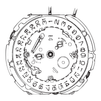
Detailed order for reassembling parts, with notes on rotor separation and part codes.

Second-Counting Wheel Part Codes

Notes on how the second-counting wheel part code varies with hand installation height.

Component Setting and Lubrication

Intermediate Wheels Interchangeability

Note on interchangeability of intermediate alarm and minute-counting wheels.

Minute Wheel Identification

Distinguishing minute-counting wheel from alarm minute wheel by pinion teeth.

Switch Lever Handling

Setting position and lubricating instructions for switch levers.

Center Wheel and Pinion Lubrication

Instructions for lubricating the center wheel and pinion.

Main Plate Lubrication

Lubricating points on the main plate, including switch lever axles and component axle holes.

Value Checking

Coil Block Resistance

Specifications for coil block resistance values.

Upconverter Coil Resistance

Specification for upconverter coil resistance.

Current Consumption

Guidelines for measuring current consumption, referencing battery installation steps.

Time Accuracy Measurement

Procedure for measuring time accuracy, noting crown position.

Function Checking Procedures

Chronograph Hands Reset

Procedure for resetting the chronograph stopwatch hands to the 12 o'clock position.

Stopwatch Function Checking

Steps to check the start, stop, and reset functions of the stopwatch.

Alarm Function Checking

Steps to check the engagement, sounding, and advancement of the alarm.

Timer Function Checking (Cal. 7T42B)

Steps to check the countdown timer function, including start, stop, and beep signals.

Related product manuals