A
Andre ReeseSep 8, 2025
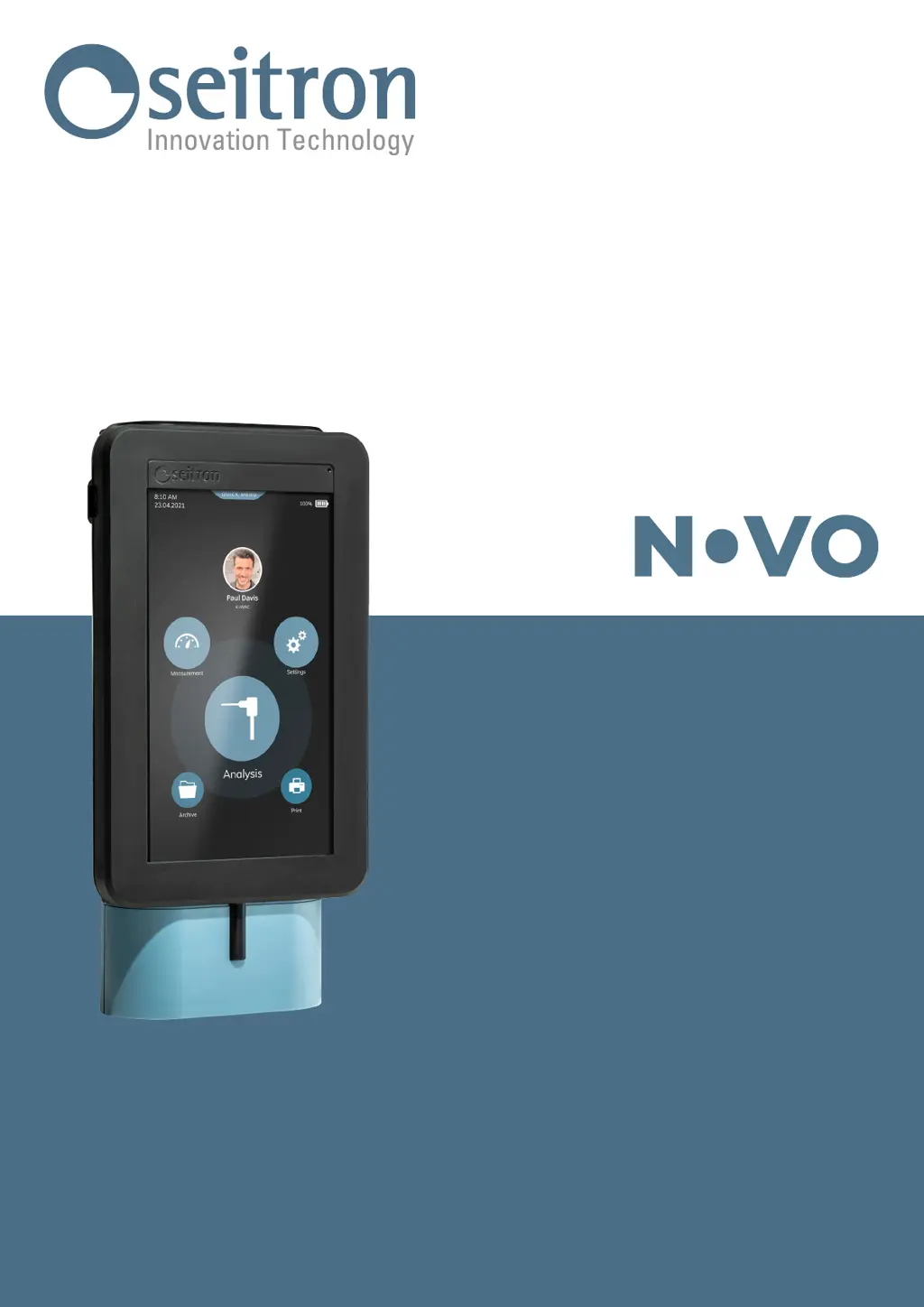
How to fix Seitron NOVO Measuring Instruments that does not turn on?
- Aamy71Sep 8, 2025
If your Seitron Measuring Instruments do not turn on when you press the On/Off button, ensure you keep the button pressed for at least 3 seconds. If that doesn't work, connect the battery charger, as the battery may be low. Also, check that the battery is correctly connected to the instrument by accessing the internal parts and inserting the battery connector into its socket on the printed circuit. If the problem persists, the instrument might be faulty, and you should contact the assistance center.