EasyManua.ls Logo

Seitron TDST24M User Manual

Seitron TDST24M
24 pages
To Next Page IconTo Next Page
Page #1 background imageLoading...
Page #1 background image
1
TDST24M000SE 032635 190619
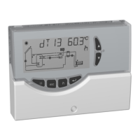
DIGITAL CONTROL UNIT
FOR THERMAL SOLAR SYSTEMS
c
The installation technician shall operate in full compliance with all the applicable technical standards in order to
grant the unit safety.
WARNING
DESCRIPTION OF THE KEYS
RESET KEY
MENU KEY CANCEL KEY KEY ‘ABC FUNCTION’
CONFIRMATION KEY
SELECTION KEYS

Questions and Answers:

Seitron TDST24M Specifications

General IconGeneral
Protection degreeIP40
ConnectionScrew terminals
MaterialPlastic
ApprovalsCE
InputPt1000
TypeThermostat
Temperature Range-50°C to +150°C
Differential Pressure RangeNot applicable
Electrical Rating5A 250V AC
Box materialABS

Summary

Overview

Technical Features

Classification Under Reg. 2013.811.EC

Regulatory classification and energy efficiency rating of the control unit.

Installation

Starting

Turning On and Off

Procedure for turning the control unit on and off using the 'esc' key.

Backlight

Activation and automatic shut-off of the display backlight.

Acoustic Signals

Functionality of the internal buzzer for feedback and alarms.

Test Function for Load Wirings Check

Procedure for testing connected loads and activating relays/PWM outputs.

Temperature and Speed Display

How the unit displays sensor temperatures and pump speed.

Automatic / ABC Operation

Explanation of Automatic and ABC modes for installation management.

Reset

Procedure for resetting the device via the hidden 'RESET' key.

Installer Parameters

Entering the Password

Procedure for entering the installer password for access.

Modifying the Password

Steps to change the existing installer password.

Control Logic

Control Logic in ABC

Explanation of the control logic for the ABC function.

Control Logic of the Safety Thermostats

Behavior of alarm relay and loads during safety thermostat activation.

Available Diagrams

P2: Setting the Thermal Data

P3: Antifrost Parameter Management

P4: Acoustic Signal Management

P5: Relay Logic Selection

P6: Integration Hours Counter

P7: Limitation of Collector Minimum Temperature

P8: PWM and 0..10V Output Settings

P9: Collector Reset Temperature

P10: Vacuum Tubes

P11: Anti-Legionella

Functions Accessible to the User

User Menu

Accessing user parameters for limited control and settings.

Displaying the Maximum Temperatures Recorded

Antifrost Activation

Troubleshooting

Warranty