16
TDST24M000SE 032635 190619
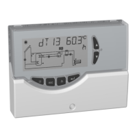
at minimum speed, while with the PWM output at maximum
value (100%) the pump runs at full speed. Of course the
pump will operate to all the intermediate speeds through the
modulation of the PWM signal between 0% and 100%.
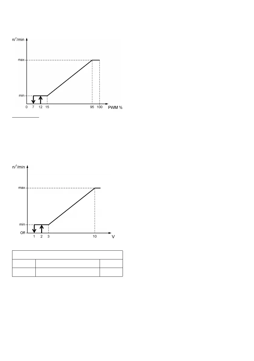
0..10V output:
The pump connected on the 0..10V output works according
to the 0V .. 10V ‘normal’ standard (N010V). With the 0V
..10V output at minimum value (0V) the pump runs at
minimum sped, while with the 0V ..10V output at maximum
value (10V) the pump runs at full speed. Of course the pump
will operate to all the intermediate speeds through the
modulation of the 0 .. 10V signal between 0V and 10V.
Setting the regulation mode of the PWM pump
Data Regulation range Default
MODO MPT / MFT / MdT MPT
Settings details
Setting MPT (differential proportional mode)
The proportional regulation of the collector pump speed is
performed, by confronting the measured temperature ∆Tr
(Collector Temp. - Boiler Temp.) with the temperature ∆T set
by the installer parameter P2. The sampling of the variables
to control the speed of the collector pump is performed every
500 milliseconds.
If the control unit is set with the ABC function activated,
the collector pump speed, if it is ON, will be equal to the set
value %MAX or VMAX, while, if it is OFF, will be equal to the
set value %OFF or VOFF.
If the collector pump is switched on after the intervention of
the ABC function, the regulation of the pump rotation speed
WILL NOT be proportional to ∆Tr.
The proportional regulation of the collector pump speed to
∆Tr, is taking into account the functioning logic (REV or
NOR) set by the parameter ERP P8 - PUMP:
When parameter PUMP = NOR (PWM2)
∆Tr < 0: The pump takes its speed at level
%OFF or VOFF.
0 ≤ ∆Tr < ∆T: The pump will have a variable rotation
speed between %ON and %MAX or
between VON and VMAX, depending
on the comparison of ∆Tr and ∆T.
∆Tr ≥ ∆T: The pump will have a rotation speed
equal to %MAX or VMAX.
To set the reference data, see parameter P8 - Parameters related
to PWM (PWM2) or 0..10V (N010V) output.
When parameter PUMP = REV (PWM1)
∆Tr < 0: The pump takes its speed at level %OFF
or VOFF.
0 ≤ ∆Tr ≤ ∆T: The pump will have a variable rotation
speed between %ON and %MAX or
between VON and VMAX, depending on
the comparison of ∆Tr and ∆T.
∆Tr > ∆T: The pump will have a rotation speed
equal to %MAX or VMAX.
To set the reference data, see the parameter P8 - Parameters
related to PWM (PWM1)or 0..10V (R010V) output.
MFT settings (xed mode)
The regulation of the collector pump speed is performed
referring the regulation to the temperature value T_FT (Fixed
point temperature control).
If the temperature on the reference sensor (collector) is
higher than the set value T_FT, then the collector pump
speed raises until reaching the maximum value only after the
‘TIME’ control has elapsed.
If the temperature measured by the reference sensor
(collector) is lower than the value set for T_FT, then the
speed is decreased down to the minimum value only after the
‘TIME’ control time has elapsed.
MdT settings (differential mode)
The regulation of the collector pump speed is performed,
by confronting the measured differential temperature
∆Tr (Collector Temp. - Boiler Temp.) with the differential
temperature ∆T set by the installer parameter P2.
If the measured differential temperature (∆Tr) between the
collector and accumulation probes is higher than the set
temperature differential (∆T) for the solar regulation, the
 Loading...