Date Code 20160329 SEL-651RA Recloser Control
3
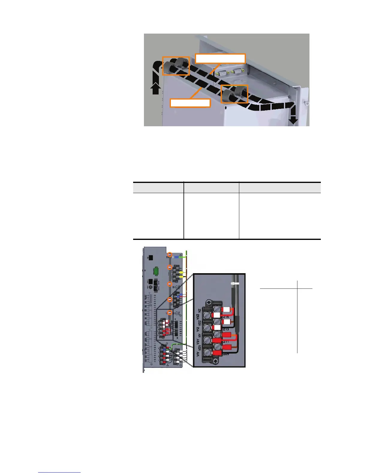
Figure 3 Secure Wires on Top of Control Module
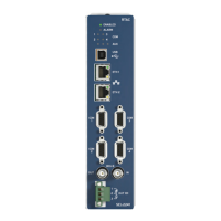
Step 5. Attach the eight-pin harness wires according to the table in
Figure 4 as required for your specific secondary input voltage
option. See Table 1 for SIV-specific wiring. Note that the
Z-side wires have white heat shrink on the ring terminals.
Figure 4 Attach Wires to Control Module
Step 6. Zip tie wires as necessary.
Table 1 SIV-Specific Wiring
SIV Option MOT Character Wire
Single phase 1 A, B, C, D only (Y side)
6 PT A A, B, C, D, E, F, G, H (Y and Z sides)
Z-side PT B E, F, G, H only (Z side)
Z-side PT D E, F, G, H only (Z side)
Y-side PT F A, B, C, D only (Y side)
Main Harness
Accessory Wires
8-Pin Wires: To:
Z09
Z10
Z11
Z12
A (Black Wire)
B (Brown Wire)
C (Red Wire)
D (Orange Wire)
Z13
Z14
Z15
Z16
E (Black Wire)
F (Brown Wire)
G (Red Wire)
H (Orange Wire)