5
Date Code 20010214 SEL-2505 Remote I/O Module
Functional Description
Functional Description
MIRRORED BITS
Decoder/Encoder
and I/O Control
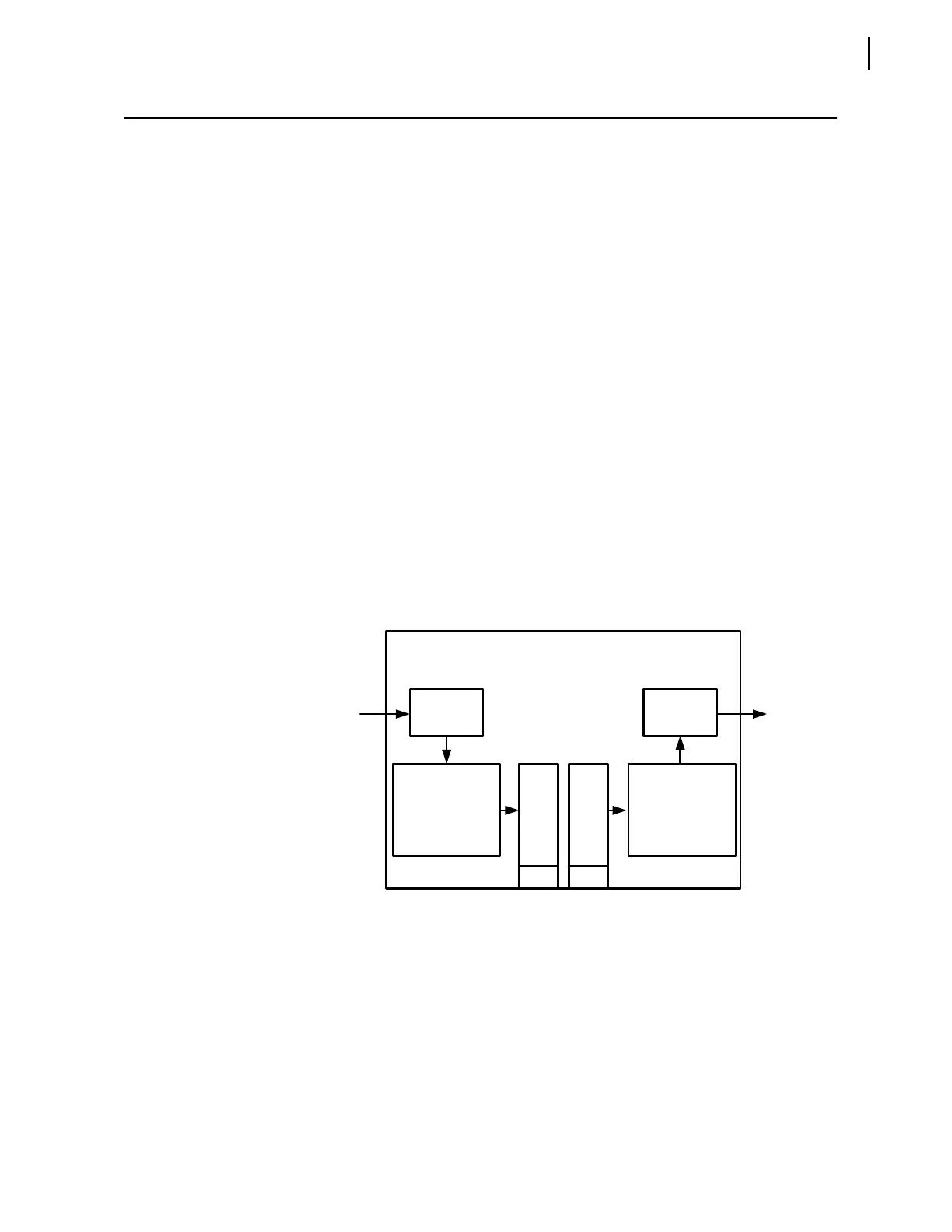
Figure 7 shows the functional block diagram of the SEL-2505. There is
aMIRRORED BIT decoder associated with the receive (RX) port and an
encoder for the transmit (TX) port. The decoder receives M
IRRORED
BIT messages, checks that the receive address matches that set by
SW3 – 4, checks for data message errors, and then decodes each
message. If a Receive M
IRRORED BIT (RMB) is a logical one for the
number of message frames set by SW5 – 8, the SEL-2505 asserts the
corresponding output contact.
If an RMB is a logical 0 for the number of message frames set by
SW5 – 8, the SEL-2505 deasserts the corresponding output contact. If
the communication channel is faulty or power is removed from the
device, the contact outputs are deasserted.
The decoder also monitors the received data and channel integrity.
Detected errors include: data errors, resynchronization, data over- and
under-run, parity, and framing errors. When it detects an error, the
SEL-2505 turns off the ROK LED and deenergizes the ALARM relay
(closing the alarm contact). If SEL-2505 detects two errors in a row, it
begins resynchronizing with the remote device. Once the remote device
receives this resynch message, it also deasserts its ROK message to
indicate a problem with the communications path.
The encoder converts the eight-contact inputs into the M
IRRORED BIT
protocol and outputs this data to the transmit fiber port. This protocol is
designed to the security requirements outlined by IEC 834-1.
Figure 7 SEL-2505 Functional Block Diagram.
SEL-2505
Remote I/O Module
8 Contact
Outputs
Fiber-Optic Port
TMBn = Transmit M
IRRORED
B
IT
n, RMBn = Receive M
IRRORED
B
IT
n
8 Contact
Inputs
Contact
Inputs
RMB1 = OUT1
•
•
•
RMB8 = OUT8
IN1 = TMB1
•
•
•
IN8 = TMB8
Contact
Outputs
TX
M
IRRORED
B
ITS
Encoder
RX
M
IRRORED
B
ITS
Decoder


 To Next Page