Next step after creating all of the connections is assembly of the controller’s casing. Before
connecting from panel with the back side please check if the rubber sealing is in the special
groove. It is important in regarding sealing and protecting controller’s main electronic plate
from any contamination. After put the from panel in together with the back side please screw
casing using included six screws 4,1x12. Before mounting the controller on the machine it is
recommended to checking of proper controller’s operating according to “first start” chapter
(2). After checking of the controller’s proper operating please use safety plugs in the places
where screws are and mount the controller on the machine. Controller’s mounting in the main
machine’s board is analogical, there is only one difference that front panel is screwed from
the inside with plastic frame and main panel casing. After all mounting please carefully pull
out cables which go out at the back side of the controller’s casing to reduce their unnecessary
length in the inside. Please be careful to not destroy any connection. After this operation
please screw PG choke to create proper sealing. Next step, in case the controller as a separate
devise, please mount it using four 4,1x10 screws on the sawing frame machine. Screws should
go though four holes in the back casing created for this purpose.
CHAPTER 2
First start
Controller’s connections checking
To check the connections, follow these steps:
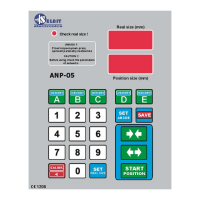
- After turning on the power, check if the adjuster displays the message: “ANP-05”.
Otherwise, check the TSS 8/001 transformer connections and retry.
- After the message “ANP-05” disappears, press the green button with arrows pointing
inwards; at this point, the adjuster should connect the reduction contactor and the value of the
dimension, visible in the “Real size” window, should decrease. Similarly, when you press the
green button with arrows pointing outwards, the adjuster should connect the increase
contactor and the dimension value in the “Real size” window should increase. If the counter is
working incorrectly, i.e. the value displayed decreases while pressing the increase button and
increases while pressing the reduction button, swap the wires, red with orange (ENCODER
connector, terminals In1, In2), and check again the accuracy of the counter. Checking the
accuracy of the counter is very important, because if the counting direction is incorrect, the
adjuster will not function.
If the connections have been checked successfully according to the above description,
you can proceed to the next step of the adjuster start-up.
 Loading...