Do you have a question about the Selec 900VPR-U and is the answer not in the manual?
Lists key features like over/under voltage, frequency monitoring, True RMS, and alarm relays.
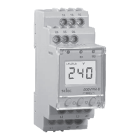
Details display, electrical connections, supply, operating range, frequency, and VA rating.
Covers trip settings for voltage/frequency and time delays (Power ON, Trip, Recovery).
Defines hysteresis ranges and accuracy for voltage, frequency, and time settings.
Describes the two relays (SPDT) and their ratings, plus LED indications for trips.
Details operating conditions, altitude, temperature, humidity, and physical dimensions.
Emphasizes following instructions for personnel and instrument safety.
Provides warnings about power disconnection and correct wiring procedures.
Illustrates the terminal layout for Relay 1, Relay 2, and auxiliary supply.
Explains how to enter the configuration menu and navigate between main and sub menus.
Details the network selection parameter and its options.
Covers configuration for Over Voltage, Under Voltage, Over Frequency, Under Frequency, and Asymmetry.
Configures Trip time delay, Recovery time delay, and Power ON delay for Relay 1.
Details settings for Phase sequence, Phase failure, Power ON Delay Mode, MOD, and Latch.
Covers configuration for Over Voltage, Under Voltage, Over Frequency, Under Frequency, and Asymmetry for Relay 2.
Configures Trip time delay, Recovery time delay, and Power ON delay for Relay 2.
Adjusts hysteresis for Voltage, Frequency, and Asymmetry.
Enables/disables password protection and sets the password for configuration access.
Option to reset all settings to their factory default values.
Explains how to set trip values and how trip indications are displayed.
The Selec 900VPR-U is a comprehensive voltage and frequency monitoring relay designed for 3-phase electrical systems. It offers a wide range of protection features, precise measurement capabilities, and user-friendly configuration options, making it suitable for various industrial and commercial applications.
The 900VPR-U continuously monitors electrical parameters in 3-phase, 3-wire, or 4-wire systems. Its primary function is to protect equipment from voltage and frequency anomalies, including:
Upon detection of a fault, the device activates one or both of its two independent alarm relays (Relay1 and Relay2), providing output signals for control or indication. The device also incorporates adjustable time delays for Power ON, Trip Time, and Recovery Time, allowing for customized response to transient conditions and preventing nuisance tripping.
Display:
Electrical Connection:
Auxiliary Supply:
Operating Range:
Frequency Range:
VA Rating:
Trip Settings:
Time Settings:
Response Time:
Hysteresis:
Resolution:
Accuracy:
Output Specifications:
Environmental Specifications:
Mechanical Specifications:
The 900VPR-U is designed for ease of use and configuration:
The 900VPR-U is a reliable and versatile protection relay, offering comprehensive monitoring and control for critical electrical systems.