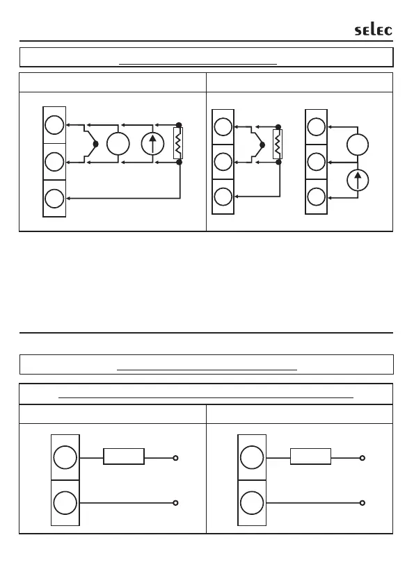
3. SENSOR INPUT WIRING
3) For 2 wire RTD short terminals 8 & 9 (for PID500) and terminals 3 & 4
(for PID110 & PID330) .
NOTE : 1) Refer input type selection in level 0 of programming menu.
2) For PID500 refer input jumper selection as in point no. 12 on page 6.
TC - Thermocouple (J, K, T, R, S, C, E, B, N, L, U, W, Platinel II).
mA - Current Input (0 to 20mA DC)
RTD - PT100.
V - Voltage Input (0 to 10 V DC).
4. CONTROL OUTPUT WIRING
4
5
LOAD
230VAC
SUPPLY
NO
COM
10
Installation
RTD2
7
8
9
TC
+
-
V
+
-
+
-
mAV
RTD3
RTD1
PID500 PID110 & 330
PID500 PID110 & 330
11
12
LOAD
230VAC
SUPPLY
NO
COM
Fig1. Output 1 - Relay to drive load (resistive load less than 1A).
5
6
7
V
+
-
mA
V
RTD2
2
3
4
TC
+
-
RTD3
RTD1
+
-
N
L
N
L