8
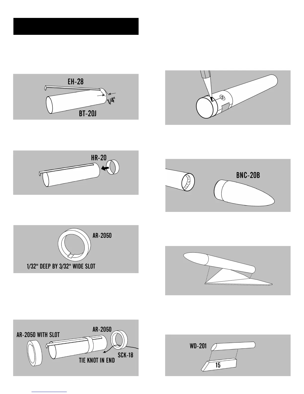
13. Using a hobby knife, punch a small 1/8”
wide slit on the engine tube (BT-20J) 1/4” from one
end. The BT-20J is 2-3/4” long. Insert one end of the
engine hook (EH-28) in the slit.
14. Slide the Retaining Ring (HR-20) over the
front of the engine tube and position it about 3/4”
from the punched end of the engine tube.
ENGINE MOUNT ASSEMBLY
15. Cut a notch 1/32” deep and 3/32” wide on
the inside of one of the centering rings (AR-2050).
This will allow the ring to clear the engine hook.
16. Tie a knot in one end of the Kevlar®
thread and pass it through the uncut centering ring.
Slide the ring onto the top of the engine tube until it
is even with the end of the tube. Slide the slotted
centering ring with the slot over the engine hook
until it is 3/4” from the bottom of the engine tube.
17
38. Check the glider nose cone (BNC-20B) for
fit, sanding if necessary. Apply a bead of glue inside
one end of the glider body tube and insert the nose
cone.
37. Cut out the Glider Marking Guide from
the pattern sheet. Wrap it around the glider body
tube about 1/4” from one end. Hold it in place with
a small piece of tape. Place a mark at both arrows
and write the corresponding letter near each mark.
Extend a line from each mark as you did with the
main body tube.
39. Apply a bead of glue along the glider
wing assembly joint. Attach the glider body tube
with the end of the tube even with the trailing edge
of the glider wings.
40. Sand one end of the thick dowel (WD-
201) so it has the same angle as the leading edge of
the glider hold-down support (15). Glue the dowel
so the front edges are aligned. Allow to dry.