Instruction Manual DS Series Senator Industrial Air Compressors
2024-10-11 © Glenco Air & Power Pty Ltd 6
2.2.6 Compressor Controller and Operation Panel
The compressor is fitted with an Air Intelligent Management System (AIMS) controller with
built-in user interface. The controller handles the automatic operation, monitoring and
protection of the compressor’s functions.
To ensure normal and safe operation of the compressor, users should be familiar with the
functions and meanings of the individual buttons and display messages on the controller. Please
refer to Appendix A for the details.
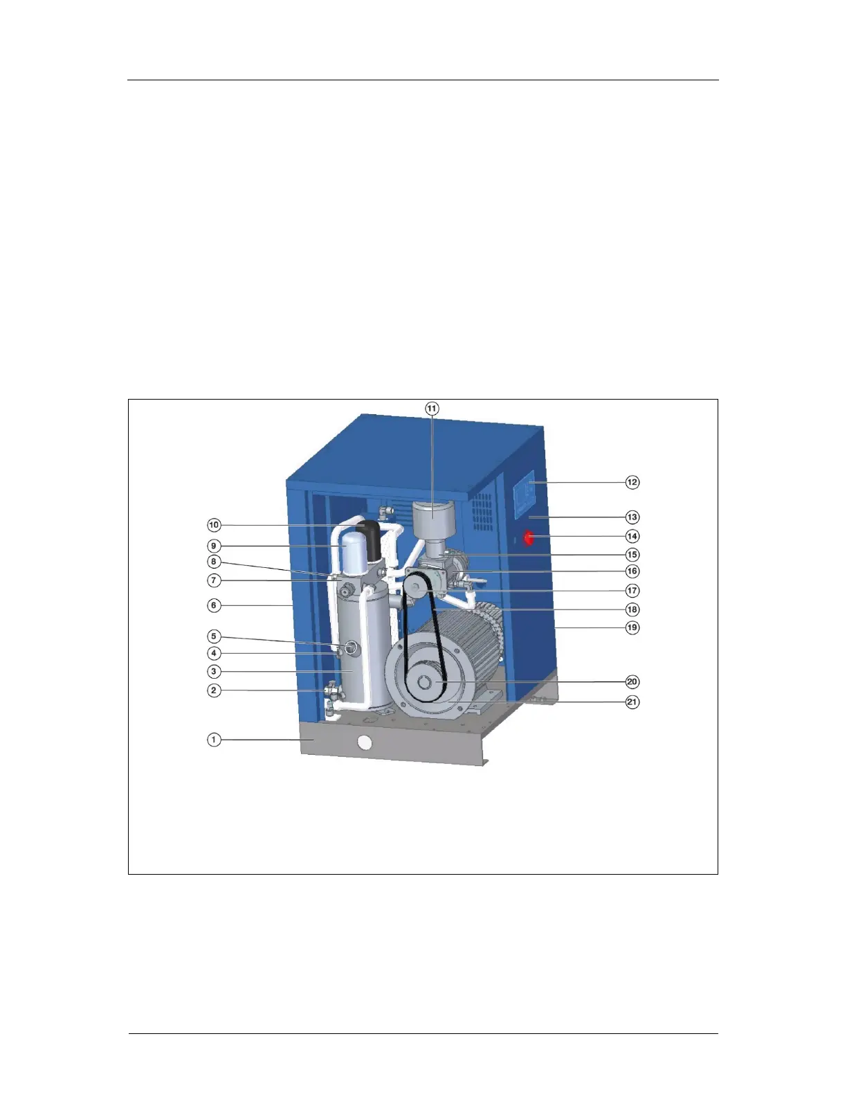
2.3 Main Components
The typical structures of the DS Series compressors are shown in Figures 2-2(a) to (d) for your
familiarisation. Please note that not all components are able to be shown and that your
compressor may differ from that illustrated.
1 Base Frame 7 Combination Valve 12 Controlle
18 V-Belts
2 Drain Valve 8 Pressure Gauge and 13 Electrical Cabinet 19 Cooling Fan (at rear)
3 Ai
-Oil Receive
Safety Valve 14 Emergency Stop 20 Motor Pulley
4 Oil Level Gauge 9 Ai
-Oil Separato
15 Inlet Valve 21 Moto
5 Oil Fill Plug 10 Oil Filte
16 Air En
6 Cooler
on side
11 Air Filte
17 Air End Pulle
Figure 2-2(a): Structure of a DS Series Air Compressor Set - Models DS4 & DS6
 Loading...