VP400 Series Video Pro Form7343A Operation Manual
39
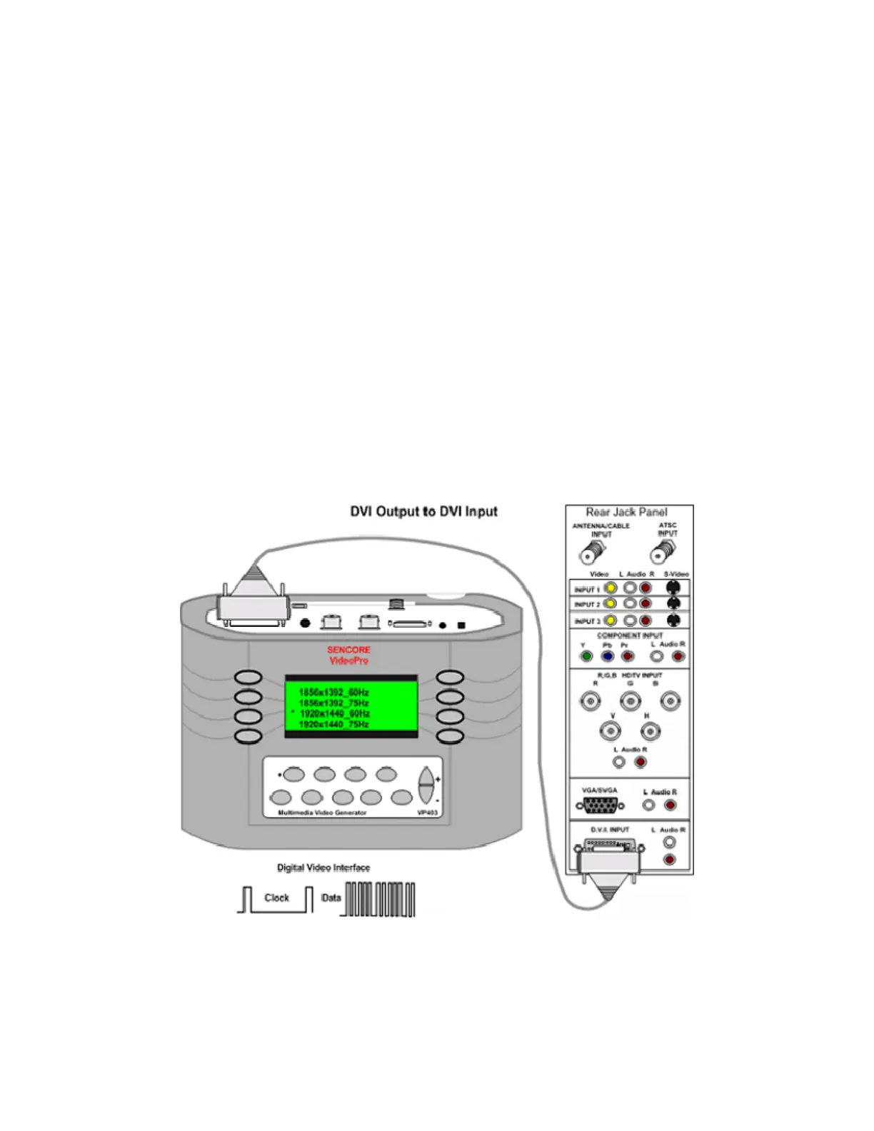
DVI to DVI Input
A digital signal interface is available to move signals from a source to a display. The video signal
is digitized into several data streams and clocked to the display. The display’s circuitry decodes
the input data to produce the original video. A DVI signal generator produces the DVI data and
clock signals comprised of video test patterns for testing the DVI inputs.
To test the DVI inputs of a display, connect
the DVI test lead (39G1060) between the
generator and the DVI inputs of the monitor.
Select either the HDTV/SDTV –DVI or
VESA/Mac – DVI selections in the Signal
Type menu. Use the HDTV/SDTV–DVI
when testing HDTV/SDTV monitors. Use the
VESA/Mac – DVI signal type when testing
computer monitors, data projectors and multi-
media projectors.
Note: Many multi-media displays are capable
of receiving and decoding both HDTV/SDTV
and VESA/Mac signal formats.
Select a signal format from the Format menu
that provides a signal resolution within the
range of the display. Select the DVI Input
from the monitor’s input menu. The monitor
should decode the DVI signal and display the
video test pattern.