13
WWW.SENIXTOOLS.COM
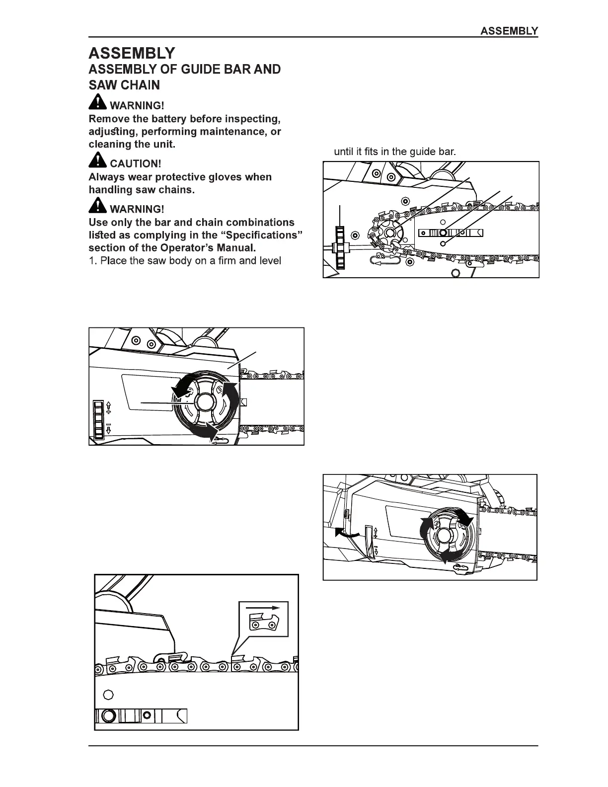
surface.
2. Rotate the side cover lock
counterclockwise to remove the cover from
the saw’s body (Figure 8).
3. Wearing protective gloves, wrap the saw
chain around the guide bar, making sure
that the teeth are aimed in the direction of
rotation (Figure 9). The chain should be
properly set in the slot running along the
entire outside edge of the guide bar.
4.Place the saw chain around the sprocket
while lining up the slot in the guide bar with
the internal bolt at the base of the saw and
the chain tensioning pin in the guide bar’s
pin hole (Figure 10). The chain tensioning
pin may need adjustment to properly align
with the hole in the guide bar. Use the
chain tensioning wheel to adjust its location
5.Turn the chain tensioning wheel to
preliminarily tighten the guide bar enough
that the chain stays in place (Figure 10).
While holding the bar still, reinstall the
cover. Make sure the tab properly line up
with the slot on the body of the saw (Figure
11). Reinstall the side cover lock and turn it
clockwise until it engages. Adjust the chain
tension.
1. Side cover lock
2. Cover
1— Sprocket
2— Internal bolt
3— Chain tensioning pin
4— Chain tensioning wheel
1
2
Figure 8 - Remove cover
Figure 9 - Correct teeth direction
Figure 10 - Install chain
Figure 11 - Reinstall cover
1
2
3
4