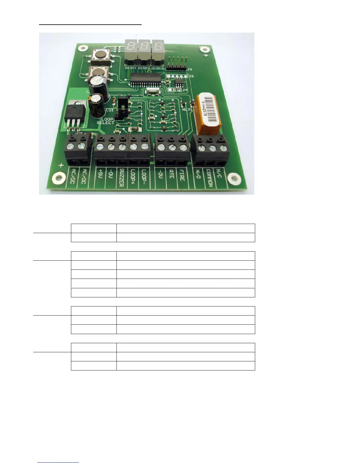
INSTALLING THE CONTROLLER
Power AC / DC 12V AC / DC
AC / DC 12V AC / DC
Reader + 5V Red from reader head
- 0V Black from reader head
Buzzer Blue from reader head
Loop + Yellow wire from reader head
Loop - Green wire from reader head
Aux -0V Bridge between RTE or Fire
RTE Request to exit input
Fire Fire alarm input (Normally open)
Relay N/O Normally open relay contact
Common Common relay contact
N/C Normally closed relay contact
(Warning: Failure to follow the wiring instructions may result in permanent damage to
the controller)


 To Next Page