Five-Year Limited Warranty.
Complete Warranty Terms Located at: sensorworx.com/warranty
INS100-D | REV 001–181220
SENSORWORX | 3 Essex Sq, Essex, CT 06426
203.678.4224 | www.sensorworx.com
© 2018 BLP Technologies, Inc. All rights reserved.
CONFIGURATION SETTINGS CONT.
FUNCTION #4 AMBIENT LIGHT OVERRIDE (PHOTOCELL)
CENTER BUTTON
Sensor will prevent lights from automatically turning on when measured light level
exceeds selected setpoint (e.g., ambient light threshold). LED blinks blue every 10 seconds
when lights are being overridden. If ambient light level falls below threshold for more
than 45 seconds, lights will switch on. During transition time, the LED will blink blue at an
increasingly faster rate. Once on, lights will stay on until occupancy time delay expires,
regardless of ambient light level.
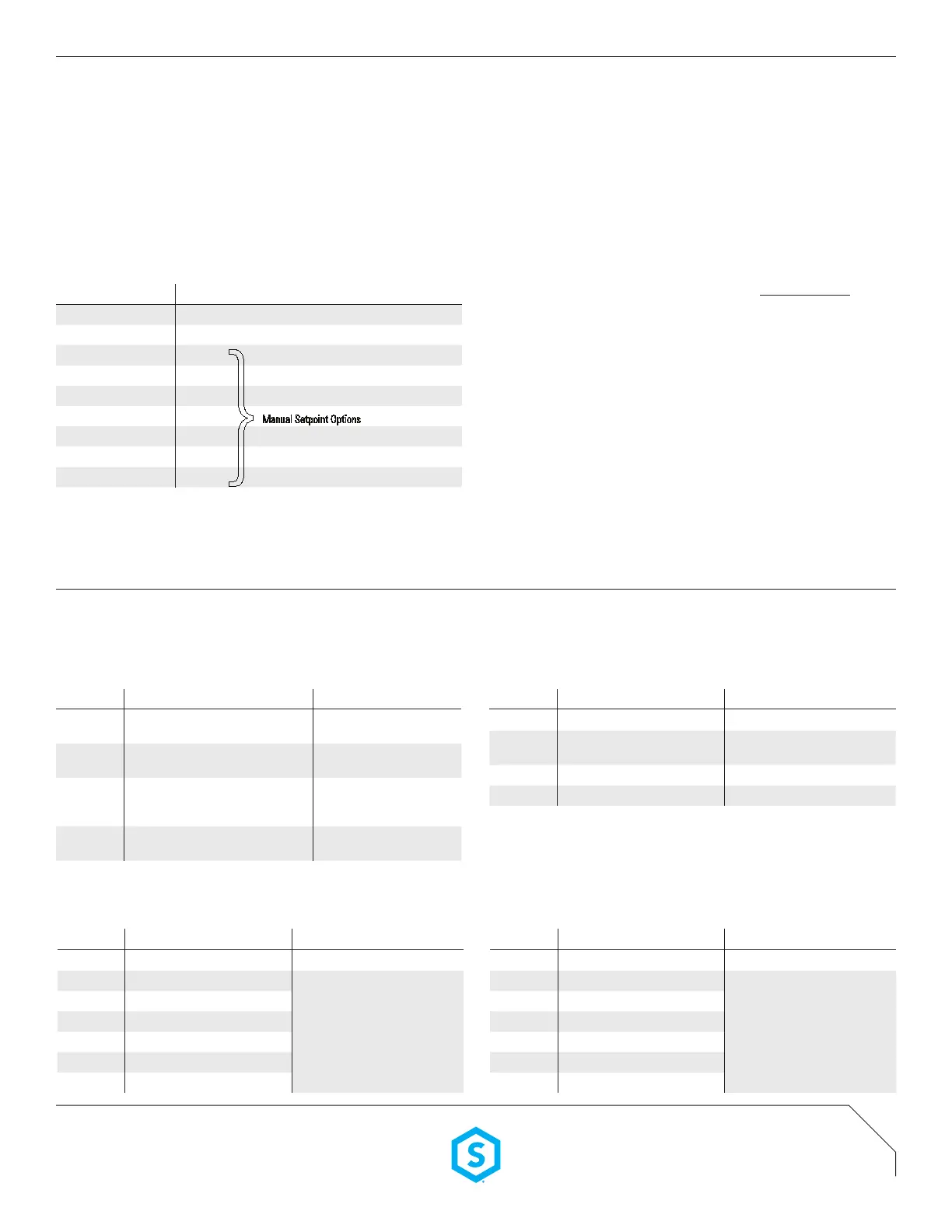
SETTING # DESCRIPTION
2 Disabled [Default]
3 Run Auto-Setpoint*
4 2 fc
5 5 fc
6 15 fc
7 30 fc
8 50 fc
9 75 fc
10 99 fc
*Instead of blinking back setting #, the value of the setpoint will be blinked back in two alternating digits:
Blue LED = 10’s digit (1-9 blinks or rapid blink or 0)
White LED = 1’s digit (1-9 blinks or rapid blink or 0)
AUTO-SETPOINT SELECTION DETAILS
A Once setting 3 “run auto-setpoint” has been selected, exit programming mode by
pressing button until LED changes from blue to white. The sensor’s LED will rapid ash
white twice conrming programming change.
B LED will then blink back blue at an increasing rate for 15 sec. In order to provide user
time to exit area in front of sensor.
C Lights will then cycle in order for sensor to calculate the controlled (articial) light
level. This is done by subtracting the light level with the lights off (relay open) from
the light level with the lights on (relay closed).
D Setpoint selection
If controlled level is less than 2 fc, setpoint will be set to measured level when
relay is open (minimum 2 fc)
If controlled level is greater than 75 fc, setpoint will be set to 99 fc
If controlled level is between 2 and 35 fc, setpoint will be set to that level plus a
reectivity ratio factor.
If controlled level is between 35 and 70 fc, setpoint will be set to 75 fc
E To check auto selected setpoint, press and hold button again until LED ashes rapidly.
Release and press button 4 times. Setpoint will be blinked back in two alternating digits:
Blue LED = 10’s digit (1-9 blinks or rapid blink or 0)
White LED = 1’s digit (1-9 blinks or rapid blink or 0)
Manual Setpoint Options
}
DETAILED DIMMING FUNCTION TABLES
FUNCTION #2 TURN OFF SCHEME
LEFT BUTTON
SETTING # VALUES NOTES
2
Unit’s relay opens immediately, switching
power off to load
Default for all models, wired in
either 2-way or 3-way
3
Unit fades dimming output down to low trim
level then opens relay.
For applications wired in 2-way
conguration only
4
Unit fades dimming output down to 0 volts
(i.e. below a connected driver’s electronic off
level). Relay remains closed
5
Unit fades dimming output down to low trim
level. Relay remains closed
FUNCTION #2 TURN ON DIMMING LEVEL
RIGHT BUTTON
SETTING # VALUES NOTES
2 Fade on to 100% of High Trim
3 Fade on to 50% of High Trim
Default for SWX-101, SWX-111,
SWX-121, SWX-131 models
4 Fade on to last user level Default for SWX-103, SWX-123
5 Fade on to current (custom) level Saves unit’s current dim level
FUNCTION #3 LOW TRIM
LEFT BUTTON
SETTING # VALUES NOTES
2 Saves current level as low trim
3 0%
Exact output voltage level depends on
Dimming Curve selected (e.g. Linear,
Log). Light output at each level depends
on driver/ballast and luminaire.
4 10% (Default)
5 20%
6 30%
7 40%
8 50%
FUNCTION #3 HIGH TRIM
RIGHT BUTTON
SETTING # VALUES NOTES
2 Saves current level as high trim
3 100% (default)
Exact output voltage level depends on
Dimming Curve selected (e.g. Linear,
Log). Light output at each level depends
on driver/ballast and luminaire.
4 90%
5 80%
6 70%
7 60%
8 50%
 Loading...