9
Servicing – 3/4", 1", 1-1/4"
General Instructions
1. Make sure the regulator is entirely depressured before servicing.
2. Carefully note location and position of all disassembled parts
to be certain reassembly is correct. Inspect each one carefully
and replace those that are worn or damaged or otherwise
unsatisfactory.
3. A moderate application of lubricant to O-Ring 13 will help
assure free stem movement and a tight seal. Similar application
of lubricant to other O-Rings or Tetraseals will help assure
their tightness. Do not use petroleum based lubricants.
4. Bolted connections should be tightened evenly and firmly.
Carefully tighten diaphragms into place. Bolts must be tight
enough to prevent leakage, but not so tight that the diaphragm
material is crushed or damaged.
5. Upon completion of servicing, make certain that regulator
installation is entirely free of leaks.
To Service Valve – 15
1. Remove bolts 38 and remove bottom cap 37 and Tetraseal 32.
2. Remove Retaining Ring 16a.
3. Remove both halves of valve holder 16b.
4. Remove valve 15 (wave washer 14 will likely remove with
the valve. Retain it for reassembly – To reassemble,
replace parts in reverse sequence.
To Service Main Diaphragm – 11d
1. Remove top cap 1, and release and remove adjustment 3 or 3a .
On high pressure model remove cap 1a, release adjustment 3a,
and remove cover 5 and button 7a. Mark or measure position
of adjustment 3 or 3a. Use this to return adjustment to this
setting during assembly.
2. Remove spring 9.
3. Remove bolts 22 and upper case 21.
4. Rotate diaphragm assembly 11 counterclockwise (this unscrews
11h from 12d) and remove.
5. To disassemble diaphragm assembly, remove nut 11a.
Carefully note location and position of all parts to be certain
of correct reassembly. Abrasive side of emery cloth washers
face against diaphragm. – To reassemble, replace parts
in reverse sequence. Make sure the screwed connection
between 11h and 12d is loose by approximately 1/2 turn.
To do this, carefully rotate diaphragm assembly 11 clockwise
until this screwed connection bottoms (do not jam it together).
Then, back-off diaphragm assembly 11 counter-clockwise
approximately 1/2 turn. The 11h and 12d screwed connection
must not be tight.
Servicing
To Service Orifice – 19
1. Remove valve 15 per section “To Service Valve-15”.
2. Unscrew orifice 19 using 1-5/8" hex socket wrench.
When replacing orifice use a moderate amount of pipe
dope on orifice threads.
To Service Seal Diaphragm – 12b
1. Remove valve 15 per section “To Service Valve-15”.
2. Remove diaphragm assembly 11 per section
“To Service Main Diaphragm-11d”.
3. Remove bolts 25 and lower diaphragm case 24.
4. Remove bolts 29 and center piece 27, and then remove
seal diaphragm assembly 12.
5. To disassemble 12, unscrew piston 12a from stem 12d.
Use a spanner wrench in notch in skirt of piston
(this can also be done by inserting a standard 7/32"
Allen wrench in the notch).
–To reassemble, replace parts in reverse sequence.
Make certain that fabric side of seal diaphragm 12b
faces upward and “rubber” side faces downward toward body.
Do not pinch loop in seal diaphragm 12b between 35
and centerpiece 27.
Periodic Inspection:
Regulators are pressure control devices with numerous moving
parts subject to wear that is dependent upon particular operation
conditions. To assure continuous satisfactory operation,
a periodic inspection schedule must be adhered with the
frequency of inspections determined by the severity of service
and applicable laws and regulations.
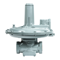
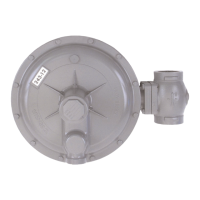
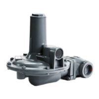
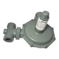
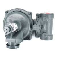
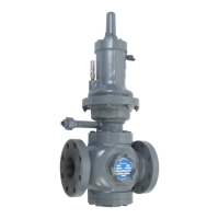
Installation and Maintenance
Model 121 Regulators
 Loading...