4
Note:
a. If upper valve assembly is too large to remove through
side opening, then remove it through bottom opening by
also removing outlet orifice 29, (remove cap screws 26
to remove orifice, and if tight, jack out using cap screws in
jacking holes).
b. Entire valve assembly may be removed intact through
bottom opening by also removing orifice 29. This method
leaves the lock-up adjustment undisturbed.
c. Use care with orifice O-ring 27.
6. To disassemble upper and/or lower valve assembly,
remove nuts 50a.
To Replace and Adjust Valves
1. Assemble upper valve assembly
(parts 50a, 50b, 50c, 50d, 50e, 50f, 50g, 50i), and lower
valve assembly (parts 50a, 50b, 50c, 50d, 50h).
Firmly tighten nuts 50a. Also, 50i should be firmly
tightened against 50a.
2. Insert upper valve assembly and screw into place.
Screw 50e or 50i into 24 until it bottoms.
Then back off 1/2 to 1 turn - this is important.
3. If orifice 29 was removed, reinstall it.
4. Insert lower valve assembly and screw into place by a few
turns (50h screws into 50e).
5. Turn upper valve assembly so Allen screw 50g is accessible
through side inspection opening.
6. Make the valve lock-up adjustment as follows:
a. Hold upper valve against its seat. This can be done by
hand, reaching through side inspection opening.
b. While holding the upper valve against its seat, screw lower
valve assembly upwards until the lower valve also touches
its seat. When both upper and lower valves are touching
their seats, they are correctly adjusted for tight lock-up.
c. Firmly tighten Allen screw 50g. This locks the adjustment
by evenly and tightly locking 50h and 50e together.
Note: If the entire valve assembly was removed intact and
Allen screw 50g has not been loosened, the assembly may
be reinstalled without making the lock-up adjustment.
7. Screw entire valve assembly up (50e or 50i screws into
24 until it bottoms). Then back off 1/2 to 1 turn –
this is important.
8. Replace side plates 38.
9. Replace bottom plate 33. Match bottom end of 50h
into 31 and/or 32, then turn bottom plate either way to
first matching bolt hole position.
To Remove Orifices
1. Remove orifice 29 per applicable steps 1 through 5 under
section “To Remove Valves”.
2. Remove inlet orifice 28 as follows:
a. Remove seal cap 1, back off adjusting screw 10,
remove housing cover 5, and remove spring.
b. Remove bottom plate 33 and then unscrew valve
assembly by grasping 50h and turning. (50e or 50i
unscrews from 24).
c. Remove diaphragm case assembly by first opening union
60 and removing cap screws 34.
d. Remove cap screws 26 and remove inlet orifice 28.
If orifice is tight, jack out cap screws in jacking holes.
Use care with O-ring 27.
e. When replacing diaphragm assembly, the threaded
connection between 24 and 50e or
50i should be
screwed together until it bottoms.
Then backed off 1/2 to 1 turn - this is important.
To Change Spring
1. Remove seal cap 1, back off adjusting screw 10,
remove housing cover 5, and remove spring.
2. Insert the new spring. Be sure it nests correctly into part 19
and travel indicator bracket 45k is in place. Also, make a
visual inspection of diaphragm 20 before inserting the spring
to be sure the roll-out is uniform and in place.
(Use a flashlight if necessary).
3. Complete steps 7, 8, and 9 under “To Assemble 441-57S”.
To Service Diaphragm
1. Remove seal cap 1, back off adjusting screw 10,
remove housing cover 5, and remove spring 14.
If used, also remove spring 14a and 14b.
2. Remove bolts 42. Then carefully remove upper
diaphragm case 8.
3. Turn diaphragm assembly counterclockwise until 24
unscrews from 50e or 50i, then remove assembly and
inspect diaphragm.
4. If a new diaphragm 20 is required, remove nut 16
and disassemble.
5. When reassembling, be sure that fabric side of diaphragm
20 will be toward the vent side of the regulator and the
rubber side of diaphragm toward the pressure side.
The gasket is always placed on the spring side of
the diaphragm.
6. Screw diaphragm assembly back into place
(24 screws into 50e or 50i until it bottoms).
Then back off 1/2 to 1 turn – this is important.
7. Fold roll into roll-out diaphragm and then carefully reinstall
upper diaphragm case 8. Diaphragm must not be pinched
between upper and lower cases 8 and 40 or 40a
. Also,
roll-out loop must be uniformly full and even. It should be
in place as shown on the cross-section drawing.
Tighten bolts 42 evenly.
8. Replace spring, etc., per steps 6 thru 9 under
“To Assemble 441-57S”.
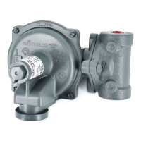
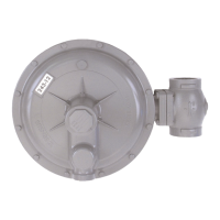
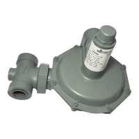
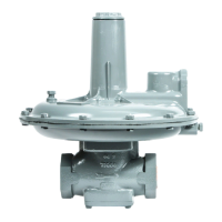
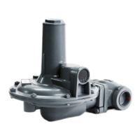
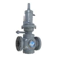
Installation and Maintenance Instructions
Model 441-57S Regulator
 Loading...