3
Servicing and Adjustment
General Notes (See illustration on pages 5 – 7)
1. Make sure the regulator is entirely depressurized before
servicing.
2. A quick visual inspection of the valve can be made by
removing inspection plates 38 from the sides of the body.
These also provide greatly improved access to the valve
when servicing or adjusting.
3. Carefully note location and position of disassembled parts
to be certain reassembly is correct. Inspect each one
carefully and replace those that are worn or damaged or
otherwise unsatisfactory.
4. The diaphragm 20, the springs 14, and all other parts
from the diaphragm up (except the 24 stem) are fully
interchangeable with the Model 461-57S Regulator.
Valve and body parts are interchangeable with other
441 Regulators (441-S, 441-X57, 441-VPC.).
CAUTION
Turn gas on very slowly. If an outlet stop valve is used,
it should be opened first. Do not overload the diaphragm with
a sudden surge of inlet pressure. Monitor the outlet pressure
during start-up to prevent an outlet pressure overload.
7. Put the regulator into operation as follows:
a. Slowly open downstream control line valve (A).
b. Slowly open downstream block valve (B).
c. Very slowly open upstream block valve (C).
8. Set adjusting screw 10 for the required outlet pressure. Turn
it clockwise to increase the pressure and counterclockwise
to decrease it. Only make this adjustment when gas is
actually flowing through the regulator. After adjustment
is complete, locknut 11 should be tightened firmly and seal
cap 1 replaced.
9. To shut down, carefully close valves (C), (B), and
(A) in that order.
CAUTION
1. Keep pipe dope and all other foreign substances out of
the control line.
2. Never install any type of automatic shut-off device,
which closes completely, between the regulator outlet
and the downstream control line connections.
3. The vent must be positioned to protect against flooding,
drain water, ice formation, traffic, tampering, etc.
The vent must be protected against nest building animals,
bees, insects, etc. to prevent vent blockage and minimize
the chances for foreign material from collecting in the
vent side of the regulator diaphragm.
5. Use lubricants sparingly and with care to avoid exposing
tacky surfaces to the gas stream. Such surfaces could
cause dirt accumulation on close clearance parts.
Use moly or silicone type lubricants.
Avoid the use of petroleum base types.
Lubricate the stem 24, the guide 50h and stem O-ring 23
with dry silicone lubricant to help assure free movement
and a tight seal.
An application of silicone base lubricant to the other O-rings
and the tetraseals in the regulator will also help assure
their tightness.
6. There is one screwed connection that must be loose.
Carefully note which one it is. All other connections must
be firm and tight.
On 2" and 3” regulators, the loose connection is between
parts 50e and 24.
On 4” and 6” regulators, the loose connection is between
parts 50i and 24.
This loose connection should be screwed together until
it bottoms, then be backed off 1/2 to 1 full turn.
7. When replacing orifices, tighten cap screws 26 evenly and
carefully to avoid stripping female threads in body casting.
8. When changing to different size valve in 4” and 6”
regulators, be sure to use the correct travel stop (Ill. No. 54).
For identification, last digit of part number is recessed into
one end of travel stop.
CAUTION
Regulators are pressure control devices with numerous moving
parts subject to wear which is dependent upon particular
operating conditions. To assure continuous satisfactory
operation, a periodic inspection schedule must be adhered to
with the frequency of inspection determined by the severity
of service and applicable laws and regulations.
To Remove Valves
1. Remove seal cap 1, back off adjusting screw 10,
remove housing cover 5 and spring 14 (also, 14a
and 14b if used).
2. Remove bottom plate 33, and side plates 38.
3. Insert an Allen wrench through side inspection opening and
loosen Allen screw 50g.
4. Unscrew lower valve assembly and remove through bottom
opening. (50h unscrews from 50e).
5. Unscrew upper valve assembly and remove through side
opening. (50e or 50i unscrews from 24).
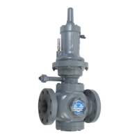
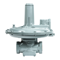
Installation and Maintenance Instructions
Model 441-57S Regulator
 Loading...