*This document replaces RM-1306-1 R11
IN-G-REG-1306-0313-01-A*
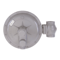
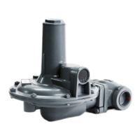
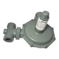
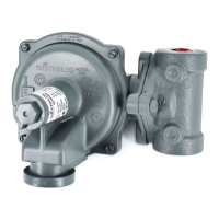
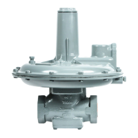
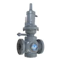
243 Service Regulators
Installation and Maintenance Instructions
Introduction
The 243 is a large capacity, general-purpose gas pressure
regulator.
Its outstanding performance and versatility make it an excellent
choice for use on industrial meter sets, combustion equipment,
boilers, unit heaters, furnaces, ovens and other applications.
Use it for natural gas, air dry CO
2
, propane, butane, LPG,
nitrogen, and others. Special materials are available for certain
corrosive gases.
In addition to the standard models and internal relief models
covered in this bulletin, the 243 is also available with low pressure
cut-off, with built-in monitor, and as a pilot operated regulator
(outlet pressures to 35 psig), a back pressure valve, a relief valve,
a vacuum regulator and a vacuum breaker. For information,
please contact your Sensus sales offi ce or authorized industrial
distributor. The 243 is manufactured in conformance with Code
B31.8.
NOTE: The term “standard” refers to non-IRV confi gurations.
Model Specifi cations
243-12-1 and 243-12-2
Maximum Inlet Pressure ................................................ 125 psi
Outlet Pressures ..............................................3½" w.c. to 3 psi
Pipe Sizes ........................................................1¼", 1½" and 2"
Diaphragm ............................................. 12" (nominal diameter)
243-8-1 and 243-8-2
Maximum Inlet Pressure ................................................ 125 psi
Outlet Pressures ......................................... 3½" w.c. to 4¼" psi
Pipe Sizes ........................................................1¼", 1½" and 2"
Diaphragm ............................................... 8" (nominal diameter)
243-8HP
Maximum Inlet Pressure ................................................ 125 psi
Outlet Pressures ....................................................... 3 to 10 psi
Pipe Sizes ........................................................1¼", 1½" and 2"
Diaphragm ............................................... 8" (nominal diameter)
Maximum Inlet Pressure
243-12 Orifi ce Size-Value 243-8
15 psi 1¼"-30° —
25 psi* 1¼"-10° —
25 psi 1"-30° 25 psi
40 psi* 1"-10° 25 psi
40 psi ¾"-30° 40 psi
60 psi† ¾"-10° 40 psi
100 psi ½"-10° 80 psi
125 psi ⅜"-10° 100 psi
125 psi ¼"-10° 125 psi
— .207"-10° 125 psi
*Applies only to 243-12 with external control line.
†80 psi for 243-12 with external control line.
Temperature Limits
Model 243 Service Regulators can be used for fl owing
temperatures from -20°F to 150°F.
Buried Service
Model 243 Service Regulators are not recommended for buried
service.
Installation and Start up
(See illustrations on page 4.)
1. Make certain that the regulator and piping are free of dirt,
moisture, foreign matter and other debris.
2. Be sure all shipping screens or covers are removed and the
regulator is installed with fl ow in the correct direction.
3. The regulator may be installed in any position—right side up,
upside down, vertical pipe, horizontal pipe, diagonal pipe, etc.
By loosening union bolts (16), the diaphragm case assembly
may be rotated to various positions in relation to the body.
Make certain union bolts (16) are retightened to hold
diaphragm case assembly in new position and to reseal.
CAUTION
The diaphragm case vent must be positioned to protect
against fl ooding, drain water, ice formation, traffi c, tampering,
etc. The vent must be protected against nest building animals,
bees, insects, etc. to prevent vent blockage and minimize the
chances for foreign material from collecting in the vent side of
the regulator diaphragm.
4. Make sure there are no leaks and all connections are fi rm
and tight. Tighten fl ange bolts evenly and fi rmly. On screwed
connections, apply pipe dope to male threads only.
5. On regulators that are arranged for an external control line,
run pipe or tubing from a ½" NPT connection in the lower
case to the control connection in the outlet piping. This
control piping should not be less than ½" in size and should
be adequately protected against breakage (regulators go
wide open if the control line is broken). In general, the control
connection should be at least 8 pipe diameters from the
regulator and in as straight a run of pipe as possible. The
connection itself must be smooth on the inside of the pipe.
Pitch the control line away from the regulator and avoid
moisture pockets. Keep the inside of the control line clean.
Never install any type of automatic shutoff device, which
closes completely, between the regulator outlet and the
control line connection.
CAUTION
It is the user’s responsibility to assure that all regulator vents
and/or vent lines exhaust to a non-hazardous location away
from any potential sources of ignition. Where vent line are
used, it is the user’s responsibility to assure that each service
regulator is individually vented and that common vent lines
are not used.
IN-G-REG-1306-1212-01-A Z_edited.indd 1 3/7/2013 2:17:19 PM