4
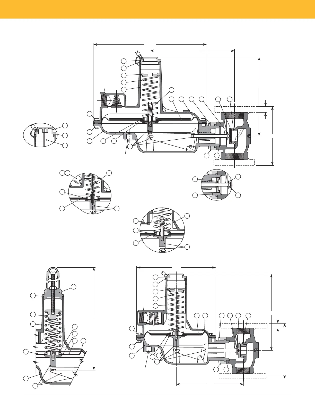
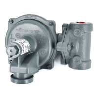
Model 243 Regulator Illustrations
243-12-2
IRV Regulator (as shown)
243-12-1
Same as IRV Regulator
except no internal relief valve
and standard cover cap as
shown in inset.
PIPE SIZES
2" fl anged ANSI 125 lb FF
1½" and 2" screwed
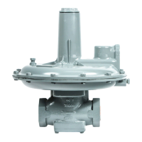
243-8HP
Remainder of regulator
same as 243-8-1
PIPE SIZES
2" fl anged ANSI 125 lb FF
1¼", 1½" and 2" screwed
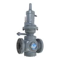
243-8-1
Standard Regulator
(as shown)
243-8-2
Same as Standard
Regulator except
Internal Relief Valve
as shown in inset.
PIPE SIZES
2" fl anged ANSI 125
lb FF 1¼, 1½" and
2" screwed
243 Service Regulators Installation and Maintenance Instructions
RIM1306-005
1e
STANDARD CAP
2a
25
25
STANDARD DIAPHRAGM
ASSEMBLY
13
27 26
11a
11d
INTERNAL RELIEF VALVE
13
11k
11a
11d
5
THROAT BLOCK
WITH O-RING SEAL
(For regulators arranged
for external line control)
21
19
18
10
16 24
⅝
"
7
" or 10"
9¾" (IRV Cover Cap)
10" (STD Cover Cap)
14
" Dia.
10
13
/
32"
2120b11a11b
11k
1
5
4
3
2
8
9
10
13
11f11d
1728
Drilled and tapped ½" NPT
on regulators arranged for
external control line
1d
15
15
/
16"
2
4
5
11e
10
13
11f
11s
11b 11a
16 24
⅝
"
7" or 10"
9¾"
10
3
/
16"
2120b11a11b
1
5
4
3
2
8
9
10
13
11f
11d
1728
Drilled and tapped ½" NPT
on regulators arranged for
external control line
Vent
1" NPT
8
19
/
32"
Vent
1" NPT
IN-G-REG-1306-1212-01-A Z_edited.indd 4 3/7/2013 2:17:26 PM