3
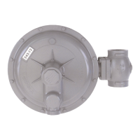
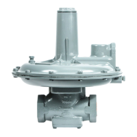
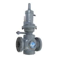
243 Service Regulators Installation and Maintenance Instructions
Illustration
Number
Description Part Number
1 Cover Cap (IRV) 143-16-005-00
1e Cover Cap (STD) 143-16-005-08
1d Tetraseal, 1½" x 1⅝" 906534
2 O-Ring #2-140 951357
2a O-Ring #2-142 951376
3 Adjustment Spring Button 143-16-009-00
4 Spring (See table, page 5)
5
243-12 Cover Assembly IRV
(includes vent valve and spring)
143-16-503-03
243-12 Cover Assembly STD
(includes vent valve and spring)
143-16-503-19
243-8 Cover Assembly
(includes vent valve and spring)
143-82-503-04
8 Flange Bolt,
5
/
16" x 1" Hex Hd. 910030
9 Flange Nut,
5
/
16"-18 Hex S.F. 921002
10
243-12 Lower Case 143-16-002-00
243-12 Lower Case (tapped
for external control line)
143-16-002-01
243-08 Lower Case 143-82-002-00
243-08 Lower Case
(tapped for external control line)
143-82-002-01
11a*
243-12 Diaphragm 143-16-150-00
243-8 Diaphragm 143-82-150-00
243-8HP Diaphragm 121-10-150-50
11b
243-12 Diaphragm Pan 143-16-017-00
243-8 Diaphragm Pan 143-82-017-00
243-8HP Diaphragm Pan 121-10-017-50
11d* Seal Washer 143-16-115-00
11e
Emory Cloth Washer
(faces against top side of 243-8HP diaphragm)
143-82-178-00
11f
Spring Guide 143-16-018-00
Spring Guide (243-8HP) 121-10-022-53
*Denotes recommended spare parts
Illustration
Number
Description Part Number
11k
Internal Relief Valve Spring, for 243-8-2 only.
(relief begins at approx. 9" w.c.
above regulator setpoint)
143-82-021-03
11k
Internal Relief Valve Spring,
(relief begins at approx. 9" w.c.
for 243-12-2, and approx. 20" w.c
for 243-8-2 above regulator setpoint)
143-16-021-02
11s 243-8HP Diaphragm Plate 121-10-022-52
13*
243-12 Coupling-Lever-Stem Assembly 143-16-530-00
243-8 Coupling-Lever-Stem Assembly 143-82-530-02
243-8HP Coupling-Lever-Stem Assembly 143-82-530-02
16 Union Bolts,
3
/
16" x 1¼" Hex 910056
17* Tetraseal (or O-Ring) 2¼" x 2½" 904075
18*
243-8 Throat Block with O-Ring Seal 143-16-508-00
243-12 Throat Block with O-Ring Seal 143-16-508-04
20b Hair Pin Cotter 143-62-118-00
21*
Valve Assembly - 10°- Buna N 143-16-511-09
Valve Assembly - 10°- Viton 143-16-511-11
Valve Assembly - 30°- Buna N 143-16-511-10
Valve Assembly - 30°- Viton 143-16-511-12
24*
1¼" Orifi ce, Brass 143-16-023-03
1" Orifi ce, Brass 143-16-023-02
¾" Orifi ce, Brass 143-16-023-01
½" Orifi ce, Brass 143-16-023-00
⅜" Orifi ce, Brass 143-16-023-04
¼" Orifi ce, Brass 143-16-023-10
.207" Orifi ce, Brass 143-16-023-11
25 Travel Stop stem 143-16-060-02
26 Warning Tag-Travel Stop 143-16-136-05
27 Warning-Tag-Body Interchangeability 143-16-136-06
28 Clamping Plate 143-16-102-01
Condensed Parts List
The following are the parts generally required in maintenance and servicing.
For a complete list of parts refer to Parts List PL-G-REG-1306.
IN-G-REG-1306-1212-01-A Z_edited.indd 3 3/7/2013 2:17:26 PM
 Loading...