5
243 Service Regulators Installation and Maintenance Instructions
Monitoring
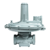
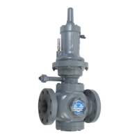
Model 243 Regulators make excellent monitors. They can act
as standby regulators installed in series and assume control if a
failure in the operating regulator permits the outlet pressure to
exceed the setpoint. It can be located in either the upstream or
the downstream position.
When a Model 243 Regulator is used to monitor a regulator with
an identical inner valve (another Model 243 Regulator), the total
maximum capacity through both regulators can be fi gured at
70% of the capacity of one regulator alone. This applies with the
monitor located either upstream or downstream.
Full Open Capacity
Use the following formulas for the full open capacity of 243
regulators:
1. Q = K
√
P
o
(P
i
– P
o
) ................. (for
P
i
less than 1.894)
P
o
2. Q =
KP
i
.............................. (for
Pi
greater than 1.894)
2
P
o
Q = maximum capacity of the regulator (in SCGH of 0.6
specifi c gravity natural gas).
K = the “K” factor, the regulator constant (from the table)
P
i = absolute inlet pressure (psia)
P
o = absolute outlet pressure (psia)
Orifi ce size: .207" ¼" ⅜" ½" ¾" 1" 1¼"
K 90 132 292 520 1100 1800 2480
Other Gases
243-RPC Regulators are mainly used on natural gas. However,
they perform equally well on LP gas, nitrogen, dry CO
2
, air and
others.
For capacities, multiply the table values on pages 6 thru 22 in
Bulletin DS-G-REG-1306 by the following correction factors:
Type of Gas Correction Factor
Air (Specifi c Gravity 1.0) 0.77
Propane (Specifi c Gravity 1.53) 0.63
1350 BTU Propane-Air Mix (Specifi c Gravity 1.20) 0.71
Nitrogen (Specifi c Gravity 0.97) 0.79
Dry Carbon Dioxide (Specifi c Gravity 1.52) 0.63
For other noncorrosive gases use the following formula:
0.60
CORRECTION FACTOR =
√ Specifi c gravity of the gas
While used primarily for natural gas services, Model 243
regulators perform equally well on LPG vapor, air, dry CO
2
,
nitrogen and other inert gas applications. Please contact your
Sensus representative for special construction which may be
available for certain corrosive gases.
NOTE: The term “standard” refers to non-IRV confi gurations.
Maximum Emergency Pressures
The maximum pressure the regulator inlet may be subjected
to under abnormal conditions without causing damage to the
regulator is the maximum allowable inlet pressure (from the table
below) plus 50 psi.
The maximum pressure the diaphragm may be subjected to
without causing damage to the internal parts of the regulator is:
243-12-1 ............................................. setpoint + 3 psi
243-12-2, 243-8-1 and 243-8-2 .......... setpoint + 5 psi
243-8HP ............................................. setpoint + 5 psi
If any of the pressure limits are exceeded, the regulator must be
taken out of service and inspected. All damaged or otherwise
unsatisfactory parts must be repaired or replaced.
The maximum pressure that can be safely contained by the
diaphragm case is:
243-12-1 and 243-12-2 ...................................... 15 psi
243-8-1 and 243-8-2 .......................................... 45 psi
243-8HP ............................................................ 45 psi
“Safely contained” means no leakage as well as no bursting.
Before using any of the above data, make sure this entire section
is clearly understood.
NOTE: The use of an internal or external relief valve is
recommended for installations subjected to no fl ow for extended
periods of time, such as pilotless ignition systems. A travel
stop stem is located in the 243-12-1 and 243-12-4 to provide
overpressurization protection to internal components during
overpressurization.
Spring Ranges
Spring Color
Outlet Pressure Range
Spring Part
Number
243-12 243-8
Red 3½" to 6½" w.c. — 143-16-021-03
Red-Black — 3½" to 6½" w.c. 143-82-021-00
Blue 5" to 8½" w.c. — 143-16-021-04
Blue-Black — 5" to 8½" w.c. 143-82-021-01
Green-Black — 6" to 14" w.c. 143-82-021-02
Green 6" to 14" w.c. 12" to 28" w.c. 143-16-021-05
Orange-Black 10" to 18" w.c. — 143-16-021-11
Orange 12" to 28" w.c. 1 to 2 psi 143-16-021-06
Black 1 to 2 psi 2 to 4¼ psi 143-16-021-07
Cadmium 1½ to 3 psi 3 to 5 psi§ 143-16-021-08
Cadmium 1½ to 3 psi 3 to 6½ psi* 143-16-021-08
Cadmium — 6 to 10 psi* 143-16-021-08
White † — 6 to 10 psi* 143-16-021-13
† White is nested inside Cadmium *Model 243-8HP only §Model 243-8-2 (IRV) only
IN-G-REG-1306-1212-01-A Z_edited.indd 5 3/7/2013 2:17:27 PM
 Loading...