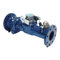
620 / 620M
LD1621INT Page 3
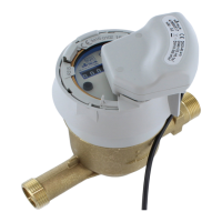
Tampering Protection
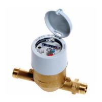
The 620 meter is designed with tamper protection
to avoid any misuse of the meter.
The plastic register is equipped with a tamper
indicator (blue pin) whose breakage provides
obvious evidence of any tampering attempt with a
screw clamp for example. When using a metal/glass
register, a clear glass break will then occur.
The meter is always equipped as standard with
magnetic protection to protect the magnetic
transmission against magnetic fields.
Any attempt to open the meter bonnet will cause
this plastic part to break.
Approvals
EC pattern approval:
in conformity with
•75/33/EEC
•71/316/EEC
DN 15 & 20 D.96/6.123.05
DN 25 & 30 B.83/32.38
DN 40 B.77/32.04
EC type-examination certificate:
in conformity with
•2004/22/EC(MID)
•EN14154:2007
•OIMLR49:2006
Q
3
2,5 DE-07-MI001-PTB002
Q
3
4 DE-07-MI001-PTB004
Certificate of compliance for potable drinking water
KTW/DVGW (D) Hydrocheck (B)
ACS (F) KIWA (NL)
WRAS (UK)
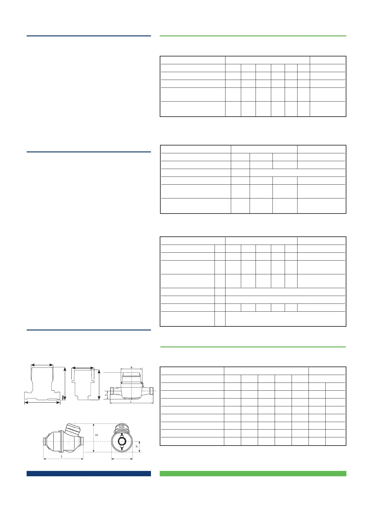
Dimensional Diagram
Performance Data
In-line Co-axial
Nominal Diameter DN mm 15 20 25 30 40 Manifold
Nominal flowrate Q
n
m
3
/h 1.5 2.5 3.5
(1)
6 10 1.5
Maximum flowrate Q
max
m
3
/h 3 5 7 12 20 3
Minimum flowrate
Q
min
l/h 15 25 35 60 100 15
(tolerance ±5%)
Transitional flowrate
Q
t
l/h 22.5 37.5 52.5 90 150 22.5
(tolerance ±2%)
In-line Co-axial
Nominal size DN mm 15 20 25 30 40 Manifold
Starting flowrate
(1)
l/h <1 <2 7 7 8 <1
Minimum flowrate
(±5%)
(1)
3 6 11 11 20 3
Transitional flowrate
(±2%)
(1)
5 12 16 16 30 5
Maximum registration m
3
10
5
Lowest resolution l 0.05
Pressure loss at Q
max
bar 0.7 0.5 0.28 0.83 0.8 0.7
Maximum Working
Pressure PN bar
16
In-line Co-axial
Nominal size DN mm 15 20 25 30 40 Manifold
Length L mm 170
(1)
190
(3)
260
(4)
260 300 n/a n/a
Width D mm 79.7 93.5 135 135 150 100 93
Total height H mm 132.7 123 186 186 193 135.6 160
Height to pipe axis h mm 15.5 37.5 68 68 75 n/a n/a
Tail inch
G
3
/
4
”B
(2
)
G1”B G1
1
/
4
”B G1
1
/
2
”B G2”B G1
1
/
2
”B G1
1
/
2
”B
piece Diameter mm 26.44 33.25 41.91 47.80 59.61 47.80 47.80
thread Pitch 1.81 2.31 2.31 2.31 2.31 2.31 2.31
Weight kg 1.0 1.6 3.7 3.8 5.0 1.0 1.35
Metrological Characteristics - EEC Directive 75/33
Operational Characteristics (manufacturer’s data)
Dimensions and Weights
Dimensional Characteristics
DN30-40
In-line version
D
h
H
L
DN15
H
D
Co-axial version
Co-axial versions
DN20-25
(1)
Also available with Q
n
6
(1) also available in length 110, 114, 115, 130, 134 and165 mm
(2) also available in length 165mm with 1” threads
(3) also available in length 165mm
(4) also available in length 198mm (with Q
3
4)
Metrological Characteristics - Directive
2004/22/EC (MID) & EN 14154
(1)
Values for R = 400
(1)
typical performance characteristics
In-line Co-axial
Nominal Size DN mm 15 20 Manifold
Permanent flowrate Q
3
m
3
/h 2.5 4 2.5
Ratio “R” Q
3
/Q
1
R 40 / 80 / 160 / 315 / 400
Maximum flowrate
(1)
Q
4
m
3
/h 3.125 5.0 3.125
Minimum flowrate
Q
1
l/h 6.3 10.0 6.3
(tolerance ±5%)
Transitional flowrate
(1)
Q
2
l/h 10.0 16.0 10.0
(tolerance ±2%)
 Loading...