Do you have a question about the Sensus PolluStat E and is the answer not in the manual?
Lists the components included with the PolluStat E meter.
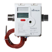
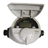
Technical specifications for the calculator unit.
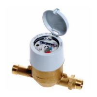
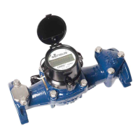
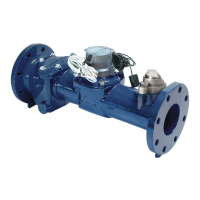
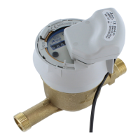
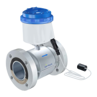
Technical specifications for the flow sensor unit.
Lists the necessary tools for installation.
Details standard and special installation of the flow sensor.
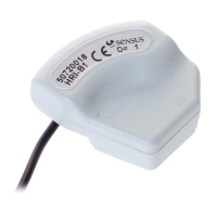
Explains the installation process for temperature sensors.
Describes how to mount and rotate the integrator unit.
Details the connection methods for temperature sensors.
Explains the user menu and its display items.
Describes the target day menu for stored values.
Details the archive menu displaying past monthly values.
Covers the service menu for meter settings and maximum values.
Explains the menu for controlling tariff functions.
Details the password-protected parameter menu.
Guides on performing functional tests and sealing the meter.
Lists and decodes potential error codes displayed by the meter.
Describes the optical data interface for settings and readout.
Details the Mini-Bus interface for connecting reading instruments.
Explains the M-Bus plug-in module for meter readout.
Covers the remote pulse plug-in module for outputting pulses.
Details the M-Bus module with inputs for external meters.
Describes the USB plug-in unit for PC connection.
Explains the USB plug-in for connecting external meters.
Covers the LONWORKS® plug-in module for building automation.
Details the process of inserting plug-in modules into the meter.
Explains the optional integrated data logger functionality.
Describes the combined heating/cooling meter version.
Guides on disassembling and assembling meter housing parts.
| Brand | Sensus |
|---|---|
| Model | PolluStat E |
| Category | Measuring Instruments |
| Language | English |