.
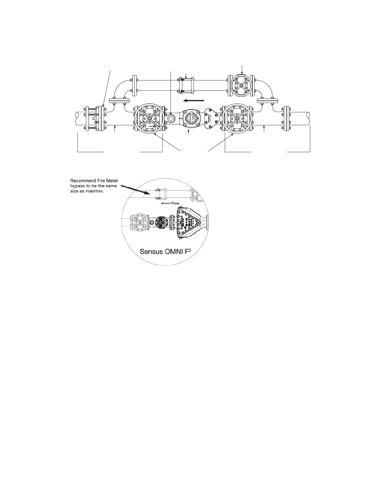
2 Dia. Minimum
Straight Pipe
Recommended
Bypass Tee
Full-Open
Gate Valve
Sensus OMNI Meter
(Shown)
2 Dia. Minimum
Straight Pipe
Recommended
Bypass Tee
Test Outlet
w/Locking
Ball Valve
Smith-Blair Coupling
Bypass Valve Closed
During Meter Use
Upstream
Downstream
Smith-Blair Flange Coupling
Adaptor w/Anchor Studs
(Optional Flexibility)
Flow
1
/
2
1
/
2
OMNI Installation 7
5. No mechanical stresses should be exerted on the meter when installed in the
pipeline. The pipeline flanges must align with the meter flanges, the distance
between the flanges must match the meter body length, and the weight of the
meter must be supported evenly. Mis-alignment stresses can cause the meter
body or flanges to crack; thus, when the pipeline is under pressure, flooding can
occur.
6. The meter must not be subjected to pressures higher than the pressure rating
pr
inted on the data sheet. Too high pressure can cause leaks or burst the meter
body.
7. Gaskets must not protrude into the pipeline or be misaligned.
8. The pipeline must be thoroughly flushed before ins
talling the meter to prevent
damage from debris.
9. The flow direction of the meter (arrow on the meter body) must correspond with
t
he flow direction in the pipeline.
10. After installation of the meter, the
pipeline must be filled with water very slowly to
prevent the meter being damaged by surges. Filling the pipe too rapidly can cause
air/water surges, which can destroy the meter insert.
11. The installation site should be chosen to
prevent air bubbles collecting in the
meter and the pipeline must always be completely filled with water. Installation of
a meter at the highest point in a pipeline must be avoided.
 Loading...