Page 4 KalGUARD
®
Installation Manual V3 04/18
Installation Advice
SYSTEM AND COMPONENT ARRANGEMENT
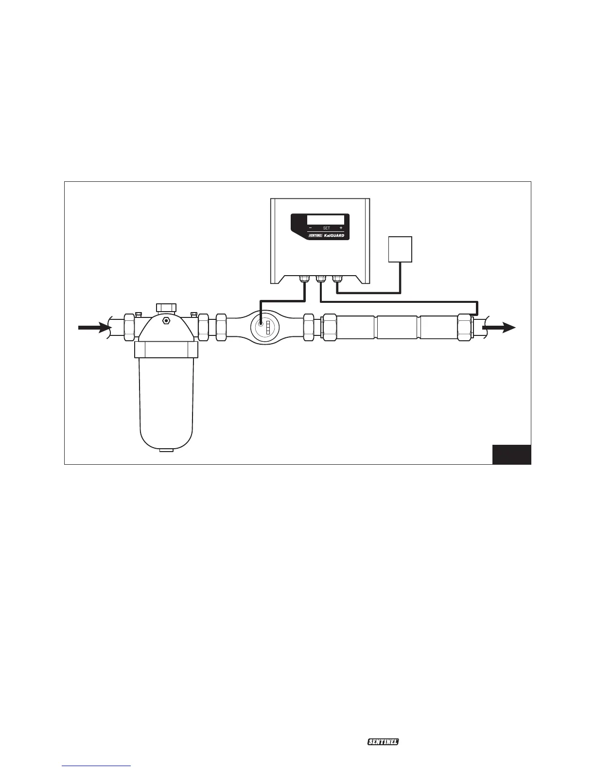
It is important to ensure that the KalGUARD system components are installed in the same
water flow line, as per Fig. 1. They should typically be arranged in a ‘side-stream loop’ to the
main water feed line. It should be possible to place the side-stream loop in or out of service by
the operation of isolation valves on the loop and a by-pass valve on the main water feed line.
KalGUARD Anode Unit
This component contains a zinc anode
which continuously doses small amounts of
zinc ions into the water passing through it to
inhibit scale formation.
KalGUARD Controller
The controller links with the water meter to
automatically match the output of zinc ions
to water flow.
25/55 µM Water Filter
Filtration of incoming mains water to
≤50µm is recommended to ensure
optimum performance of the equipment.
For all pipe sizes up to 108mm (4"), the filter
supplied will be a “stacked disc" type. The
filter must always be installed upstream of
the KalGUARD anode unit.
Water Meter
The water meter provides essential data
to the KalGUARD controller to ensure
intelligent activation of the KalGUARD anode
unit. It is NOT intended for direct paralleling
with a BMS for volumetric water coupling
(see later – “Installation of Electrics/
Electronics").
Following the completion of the
installation, please refer to the check list
on page 14 before contacting Sentinel on
01928 704 330 to arrange
COMMISSIONING.
Filter
Controller
Anode UnitWater
Meter
Mains System
Mains 240V/50Hz
(Single phase)
Fig. 1
 Loading...
