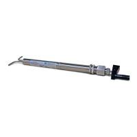
Sentry VREL Control Valve 7
A VREL valve with Type 1 or Type 3
connectors can be easily disassembled.
Type 2 connectors must be cut out.
For Type 2 and Type 3 connections, the
customer must weld the system tubes
either to the socket weld ttings (Type2),
or to the loose weld adapter (Type3). In
the case of Type 3 connections, be sure
to slide the nut onto the tube before
welding the adapter. See Figure 1.
Operation
During operation, the VREL valve may become hot. Do not touch. Use care not to touch adjacent
hot sample lines.
When starting up a sample line that includes a VREL valve, always be sure that the rods are
fully inserted before opening the sample isolation valve (turn handle clockwise to insert rods).
The VREL valve is not a positive shut-o device. Even when fully closed, approximately 150 cc/
min sample ow through the VREL valve is possible. When the rods are fully inserted, the yoke
bottoms in the barrel. When the rods are fully retracted, the yoke is stopped by the seal.
Do not try to turn the handle by using extra force. The threads will be damaged.
After opening the isolation valve fully, adjust the setting of the VREL valve until the
desired ow is established. Turning the handle clockwise will decrease ow; turning
counterclockwise will increase ow.
Clean in place
Isolate the sample ow before cleaning the VREL valve. When performing this cleaning
operation, the sample pressure is not being reduced by the VREL valve. Failure to isolate the
sample ow could result in serious injury and/or cause damage to pressure-sensitive equipment
downstream from the VREL valve.
Since corrosion products, scale, and other foreign matter may be present in sample lines,
plugging of the VREL valve is possible. To clean, fully retract the rods by turning the handle
in a counter-clockwise direction. Allow the obstruction to clear. Readjust the setting of the
VREL valve until desired ow is established.
 Loading...