DAL 1965
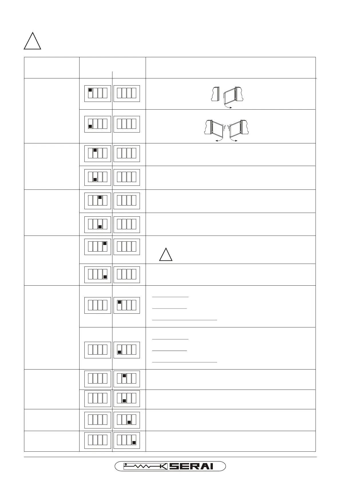
SETTING OF EACH INDIVIDUAL MICRO SWITCH
DESCRIPTION OF THE FUNCTIONING
FUNCTIONING
Single wing logic: just the output indicated with M1 is controlled
Double wing logic: outputs M1 and M2 are controlled (M2 wing
opening delay)
GATE CONFIGURATION
1 2 3
ON
4 1 2 3
ON
4
1 2 3
ON
4 1 2 3
ON
4
ENABLES/DISABLES
IMMEDIATE CLOSURE
FUNCTIONING WITH
PASSAGE ON
CLOSURE PHOTOCELL
1 2 3
ON
4 1 2 3
ON
4
1 2 3
ON
4 1 2 3
ON
4
Immediate closure function enabled: the engagement and
disengagement of the closure photocell makes the gate re-close (when
the gate is open) automatically after 5s.
Immediate closure function disabled
Hammering activated: the electric lock is activated during a brief
closure phase against the stops and is deactivated after the start-up of
M1.
Hammering deactivated: The electric lock is activated just after the
start-up of M1 and is deactivated a little after the start-up of M1.
1 2 3
ON
4 1 2 3
ON
4
1 2 3
ON
4 1 2 3
ON
4
1 2 3
ON
4 1 2 3
ON
4
1 2 3
ON
4 1 2 3
ON
4
ELECTRIC LOCK
HAMMERING
1 2 3
ON
4 1 2 3
ON
4
1 2 3
ON
4 1 2 3
ON
4
PEAK ON START-UP
Peak on start-up activated: on start-up, the motors are powered at
maximum voltage for 2s.
RECOMMENDED ESPECIALLY IN THE WINTER PERIODS
Peak on start-up deactivated: on start-up, the motors are powered at
the voltage set with the potentiometer.
ATTENTION: in this case, there may be difficulties on
start-up if the force is regulated low
1 2 3
ON
4 1 2 3
ON
4
1 2 3
ON
4 1 2 3
ON
4
CLAMPS 11-12
FUNCTIONING MODE
Open gate indicator light output: flashing during gate movement, on
with gate open and off with gate closed
!
ATTENTION:
The micro switches must be regulated when the control unit is not powered. The regulations made
to the micro switches become active on switch-on.
We recommend, after having adjusted the micro switches, to program the work times (see control
unit programming).
!
MICRO SWITCHES
SETTING
SW 2SW 1
1 2 3
ON
4 1 2 3
ON
4
1 2 3
ON
4 1 2 3
ON
4
DO NOT USE
DO NOT USE
Leave in OFF
ENABLES/DISABLES
STEP-BY-STEP
FUNCTIONING
Step-by-step function disabled
During opening: the sending of a START control is ignored, the gate
continues to open
During closure: the sending of a START control blocks the gate for a
few seconds and then it re-opens
During the gate open pause: a START control annuls the pause time
and makes the gate close immediately
Step-by-step function enabled
During opening: sending a START control causes the movement to
stop, a successive one causes the gate to close
During closure: sending a START control causes the movement to
stop, a successive one causes the gate to open
During the gate open pause: a START control annuls the pause time
and makes the gate close immediately
Electric lock output: impulse control for electric lock whose
functioning depends on the position of SW1dip3
Leave in OFF
Page 6/12
CR/41/24 I E
 Loading...