DAL 1965
CABLES’ PASSAGE
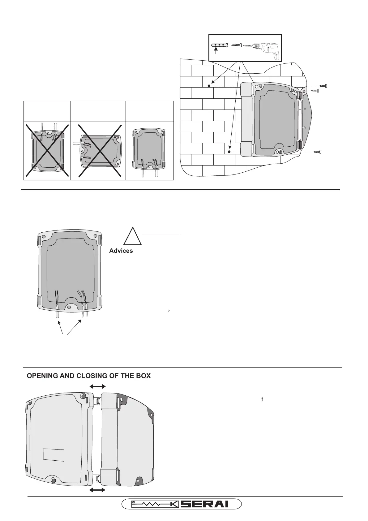
Fortheentryofthecables,inthelowerpartofthecover,holesarealreadypreparedfortheglandsPG11andPG
13,5
Cablepassage
!
ATTENTION: closetightlyalltheentriestoavoidinsects
passageandsopossibledamages.
Pag.2/10
CR/41E
WALL FIXINGOFTHECONTROL PANEL
Wesuggesttoinstallthedevicenearthegate,inorder
tohavetheminimumlenghtofthecablesforthe
connectionwiththewholesystem.
Thecontrolpanelhastobefixedwiththeholesforthe
passingofthecablesdownwards
NO NO YES
Ø6÷8mm
aaaaaa
aaaaaa
aaaaaa
aaaaaa
aaaaaa
aaaaaa
OPENING ANDCLOSINGOFTHEBOX
Advices for generical spaces connections, according to Italian Law ( CEI 64-8 ).
1.Predispose at the bottom of the system an omnipolar disconnecting switch with
distance between contacts of 3 mm or more. On alternative choice it is possible to use
a magnetothermic switch of 10A.
2.Make any kind of connections with no power supply on the system, or with the
disconnecting switch on “ open “ position ( symbol “0” ). Particularly, the control panel
must never be supplied during the wiring, nor when inserting the expansion cards.
3.During the installation use following wires.
- For control panel, motors and electric lock power-supply: 1,5mm² for max. lenghts of
19m, section 2.5mm for lenghts up to 31m
- For the flashing light: section 0.75mm² for max. lenght of 3m, section 1.5mm² for
lenght up to 19m
- For low voltage lines and current, such as photocells, command buttons,
electromechanical key, sensitive edge and other safety devices: section 0.5mm² for
max. lenght of 50m, section 0.75mm² for lenght up to 100m.
2
Whenyouopenthebox,controlthatthehingesexitfromtheir
locationinorderthatthecovercanremainopenduringthe
electricalconnections.
Closecarefullythecover,thehingeshavetobecorrectly
inserted.
Closethecoverwiththescrews.