EasyManua.ls Logo

Serai CR/41 - User Manual

Serai CR/41
10 pages
Print Icon
To Next Page IconTo Next Page
Loading...
INSTALLATIONOFTHECONTROL PANEL CR/41
Placethedevicenearthegate,inordertohavetheminimumlenghtofthecablesforconnectionwiththesystem.
Wesuggesttoplacethecontrolpanelunderacoverorinaplacewithtwolateralwalls,toprotectitagainstthe
weatherconditions.Moreoverfixitat1,5mheightsotobefarfromchildren.
WHEREPLACINGTHECONTROL PANEL
Thecontrolpanelissuppliedfromfactorywiththeopeningtowardstheleftside.Itispossibletochangetheopening,
pleasefollowthebelowinstructions:
Insertascrewdriverintheholeforthehinges-fixinginthe
backside(asshowninthepicture)andpullthecover,
pressingthefixing“tooth”(picture1)
Fig.1
Insertascrewdriverintheholeforthehinge-fixingwhichisin
thefrontsideofthecoverandpullthehingepressingthe
“tooth”(picture2)
Fig.2
DAL 1965
Installthehingesontherightsideofthebackcover,
insertthemwiththefixing“tooth”towardstheindoor
partofthecoveruntiltheclick(picture3)
Fig.3
COVEROPENING:TOWARDSTHERIGHTSIDE
Pag.1/10
CR/41IE011002072007
ATTENTION: Thisoperationhastobemadebeforethe
fixingonthewall.
!
E R A IS
GATEOPENERSDEPARTMENT
Question and Answer IconNeed help?

Do you have a question about the Serai CR/41 and is the answer not in the manual?

Summary

Installation of the Control Panel CR;41

Where to Place the Control Panel

Guidance on optimal placement of the control panel for connectivity and protection against weather.

Changing Cover Opening Direction

Instructions for reversing the control panel cover to open towards the right side.

Wall Fixing and Cable Management

Control Panel Wall Mounting

Recommendations for securely fixing the control panel to a wall using provided holes.

Cable Entry and Passage

Details on routing cables through prepared glands and ensuring tight seals.

Opening and Closing the Box

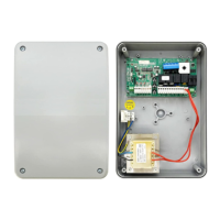
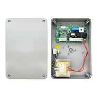
Procedure for opening the control panel box and correctly reinserting hinges.

Connection Diagram and Terminal Functions

Wiring Diagram Overview

Schematic illustrating connections for motors, lights, safety devices, and power supply.

Terminal Connection Descriptions

Detailed explanation of each clamp's function for inputs and outputs.

Fuses and Additional Relay

Information on fuse types and the function of the additional relay.

Motor Force and Electrical Connections

Adjusting Motor Force

Guide to setting motor force via the 'Power' trimmer, considering temperature variations.

Motor Electrical Wiring

Instructions for connecting motors, respecting cable colors and using 1.5mm² section.

Ground Connection

Procedure for establishing a proper ground connection for motors and the system.

Dip-Switch Configuration

Gate Type Configuration

Setting dip-switches SW1/SW2 for single or double-wing gate operation.

Slow-Down Speed Settings

Configuring slow-down speed to HIGH or LOW using dip-switches.

Final Push in Closing

Activating final push for better electric lock engagement at the end of closing.

Electric Lock Kick-Back

Setting dip-switches for electric lock activation during closing phase.

Starting Acceleration Settings

Configuring initial motor power boost for acceleration.

Gate Movement Impulse Control

Impulse Sending Modes

Describes how start impulses affect gate movement in step-by-step modes.

Photocell;Sensitive Edge Entry

Functionality of the entry for opening photocell or sensitive edge.

LED Indicator Meanings

Explanation of the status indicated by each LED on the control panel.

Control Panel Programming Procedures

Double-Wing Gate Programming

Setting working time and slow-down for double-wing gates.

Automatic Reclosure Programming

Setting and activating/deactivating automatic reclosure for the gate.

Specific Gate Programming

Single-Wing Gate Programming

Procedure for setting working time and slow-down for single-wing gates.

Automatic Reclosure Settings

Detailed steps for activating or deactivating the automatic reclosure feature.

Transmitter Code Learning

Transmitter Compatibility

Overview of compatible transmitters and code storage limits.

Learning Start Code

Procedure to program transmitters for the primary 'start' function.

Learning Pedestrian Code

Procedure to program transmitters for the secondary 'pedestrian' function.

Erasing Stored Codes

Instructions on how to clear all programmed transmitter codes.

Technical Data and Receiver Expansion

Increasing Transmitter Capacity

Options for expanding the number of programmable transmitters.

Receiver Installation

Guidance on inserting the SOG/4A receiver into the control panel.

Control Panel Technical Specifications

Key technical data including power supply, motor specs, and operating temperature.

Serai CR/41 Specifications

General IconGeneral
CategoryControl Panel
ModelCR/41
Power Supply24V DC
DisplayLCD
Operating Temperature-10°C to +50°C
CompatibilityIndustrial automation systems
CertificationsCE, RoHS

Related product manuals