CR/41E
DAL 1965
Pag.4/10
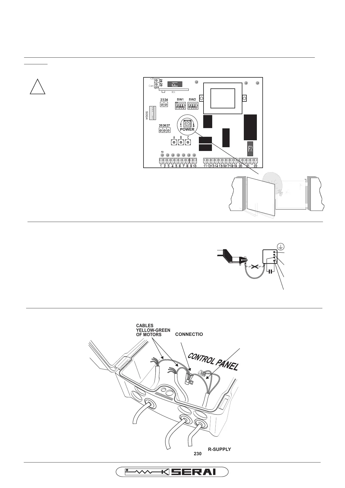
ELECTRICAL CONNECTIONOFTHEMOTOR
Connectthemotorstothecontrolpanelusingcableswith1,5mm
CABLELIGHT BLUE:Common
CABLEBROWN: Open/Close-Capacitor
CABLEBLACK: Open/Close-Capacitor
CABLE YELLOW-GREEN: Ground
Thefollowingindicationshavetoberespected(CEI64-8):
- Connectthecableyellow-greentoagoodgroundsystem
- Installatthebottomofthesystem,anomnipolarswitchwithatleast
3mmasopeningdistancebetweenthecontacts.
²section.
Respectthecolourofthecablesasfollows:
YELLOWGREEN=
GROUNDCONNECTION
LIGHTBLUE=
COMMON
BLACK=
OPEN/CLOSE
BROWN=
OPEN/CLOSE
SI
12,5µF
450V
NO
!
Fig13
ATTENTION:thehigh
temperaturescause
differentexpansions
inallmaterials,
includingthematerial
ofourproducts.For
thisreasonwe
recommendtocontrol
themotorforce
adjustingeachwinter
andsummerinthe
beginnigofeach
season.
differenciesinthe
summerandwinter
GROUNDCONNECTIONBETWEENMOTOR ANDTHEHOUSE
MOTORFORCE ADJUSTMENT
Thesettingofthemotorforceismadebychangingthevoltagethroughthetrimmer“Power”inthecontrolpanel
CR/41.
TheinstallationhastobecarriedoutinthefullrespectofthecurrentLawsconcerningthegateautomaton.
Pleaseconsiderthattheresponisibilityofthesystemanditsworkingrespectingthe“standards”isofthe
installer.
F1
F2
ON
SW1
SW2
3
4
5 6
7
8
POWER
+
-
ON
PED START STOP FOTO FOTO AP FINECH FINE AP
DL9 DL8
DL10
1 2
9
10 11121314 1516171819 20 21 22
272526
2324
SET BREAK WORK
A B C
Com
+24
spia
RX
CABLES
YELLOW-GREEN
OFMOTORS
CONNECTION
CLAMP
CABLE
POWER-SUPPLY
230V~
CABLE
MOTOR2
CABLE
MOTOR1
CABLE
YELLOW-GREEN
HOUSESYSTEM
 Loading...