DAL 1965
DAL 1965
Pag.3/10
CR/41E
F1
F2
ON
SW1
SW2
3
4
5 6
7
8
POWER
+
-
ON
PED START STOP FOTO FOTO AP FINECH FINE AP
DL9 DL8
DL10
1 2
9
10 11121314 15161718 19 20 21 22
272526
2324
28
29
OPEN
CLOSE
COMMON
230V~±10%
50/60Hz
F
N
FLASHING-LIGHT
230V~
COURTESY LIGHT
230V~
OPEN
CLOSE
COMMON
M2M1
PED
NC
NC
CLOSING
PHOTOCELLS
RECEIVERTRANSMITTER
OPENING
PHOTOCELLS
RECEIVERTRANSMITTER
NC
NC
NO
NC
NO
PEDESTRIAN
START
STOP
ELECTRIC-LOCK
12Vac15VA max
EX.SERAIM/83/1
24Vac
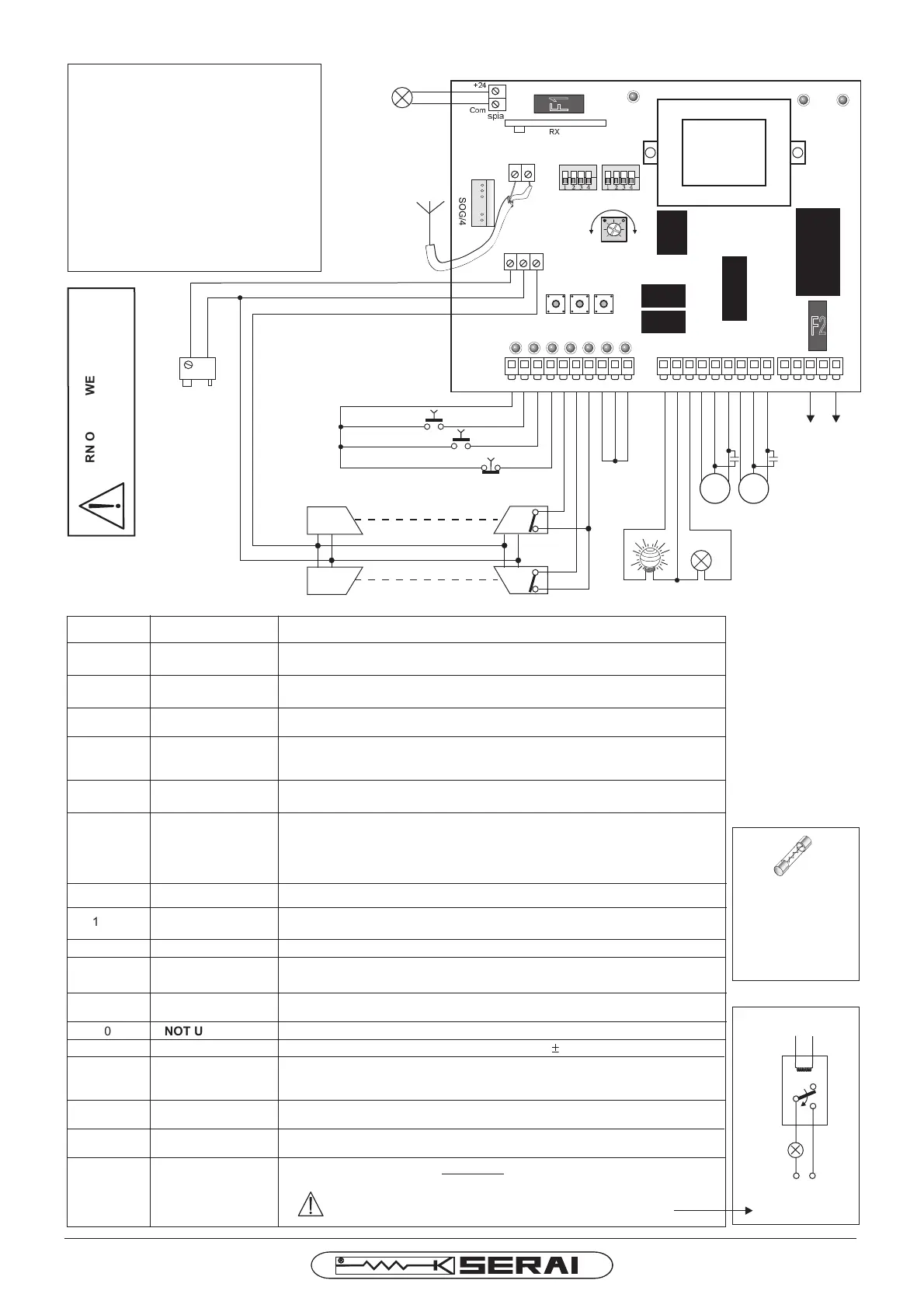
CONNECTIONDIAGRAM
CLAMPS
CONNECTIONS
DESCRIPTION
21-22
POWERSUPPLY
Entryforelectroniccardpowersupply230Vac 10%50/60Hz
±
11-12
FLASHINGLIGHT
Outputforflash-lightpower-supply(230Vac- ),forlampswithout
theinsideelectronic-forex.SERAIRZ/20F-
max50W
12-13 COURTESY LAMP Outputforcourtesylamp(230Vac- ):switched-onfor90sec.aftertheSTOPmax100W
14-15-16 MOTORM1
OutputformotorM1power-supply(14=common,15=opening,16=closing)for
singlewingorpedestrianopening(thewingtowhichisconnectedtheelectriclock)
26-27
PHOTOCELL
POWER-SUPPLY
Outputforpowersupply24Vac( )foraccessoriessuchasphotocellsmax500mA
6
OPENING
PHOTOCELL /
SENSITIVEEDGE
8-9
NOTUSED
Makeashort-circuitonthecommonwithjumpers.
5
CLOSING
PHOTOCELL
2
4
PEDESTRIAN
OPENING
Entryforthepedestrianopening(contactNO).WithDIP1SW1OFFitopens
onlythewingconnectedtoM1.WithDIP1SW1ONitopensthewingfor7sec.
STOP
EntryfortheSTOP (contactNC):whenpressedtheworkingofthemotorsis
interrupted,ifpressedduringthepausetimewhenthegateisopen,the
automaticreclosureiscanceled.
3
START
OPENING
Entryforthestartdrive(contactNO)openingandclosingwithstep-by-step
function.
WithDIP4SW2OFF:entryforphotocellactivatedinopeningand
closingphase(contactNC).Ifobscuredduringopeningthegate
stopsuntilthephotocellsremainsobscured.Duringclosingthegate
stopsandreversesthemovement.
WithDIP4Sw2ON:entryforsensitiveedge(contactNC).
Entryforphotocellsactivatedonlyinclosingphase(contactNC).If
obscuredduringtheclosingphaseitstopsthegateandreverses
1-7-10
COMMON
ENTRIES
Commonclampsoftheentries
17-18-19 MOTORM2
OutputformotorM2power-supply(17=common,18=opening,19=closing)
formotorwithdelayedopening(gatewith2wings)
25-26
ELECTRICLOCK
Outputforelectric-lock12Vac15VA max
23-24
ANTENNA
INTEGRATED
RECEIVER
Entryfortheconnectionoftheantennatotheintegratedreceiver
(23= 24= )SHIELD ANTENNA
28-29
OPENGATE
SIGNAL
Output24Vdc(28 ,29 ) fortheconnectionoftheopen-
gatesignal.
+ -
ATTENTION:toconnectlampswithabsorptionmorethan
50mA,itisnecessarytouseanadditionaloutsiderelay.
max50mA
DELAY
INOPENING
SET BREAK WORK
A
B
C
Com
+24
20
NOTUSED
spia
12Vac
RX
TURNOFFPOWERSUPPL
Y
BEFOREWIRING-UP
ADDITIONAL
RELA
Y
24Vdc-max50mA
2928
LIGHT
POWERSUPPLY
LIGHT
FUSES:
F1=2A 250V~
-
F2=5A 250V~
-POWERSUPPLY
ACCESSORIES24V-
230V-
SW1= Dip-switchestosetthecontrolpanel
A= Push-buttontoenterintoprogramming
(SET)
B= Push-buttontoprogramthetimes
(BREAK)
C= Push-buttontoprogramthetimes
(WORK)
POWER= Trimmertoadjustthemotorforce
SW2= Dip-switchestosetthecontrolpanel
LIGHT24Vdc
max50mA
 Loading...