EasyManua.ls Logo

Serai KIT/30 F - User Manual

Default Icon
18 pages
Print Icon
To Next Page IconTo Next Page
Loading...
Page 1/18
KIT/30-39F I E
!
Thank you for choosing a SERAI ELETTRONICA product, which we are confident will perform to your requirements.
Please be advised that you are about to fit a system classified as “a power-operated drive designed to move automatic ga-
tes and doors in commercial or residential buildings accessed by vehicles and persons”, and as such, the system must be
considered potentially hazardous. By law, you are responsible for rendering this equipment as “safe” as is reasonably pos-
sible.
Installation and maintenance of equipment of this kind must therefore be carried out by skilled, qualified and trained
personnel, working in a professional manner, as provided for by law n. 37/08 and any subsequent amendments and
supplements. The law in question prohibits the construction of these types of systems by non-qualified personnel.
SERAI manufacturing complies with the following legislation:
Applicable directives for the CE marking :
Machines: 2006/42/EC
Low Voltage: 2006/95/EEC
Electromagnetic Compatibility: 2004/108/EEC
General applicable standards:
Electrical Safety: IEC EN60335-1 + IEC EN60335-2-103
Electromagnetic Compatibility - Emissions: CEI EN61000-6-3
Electromagnetic Compatibility - Immunity: CEI EN61000-6-
Apart from the legislation mentioned above, you are also reminded to comply with the following standards during the
installation phase.
General applicable standards:
Safety of electrical systems in non-specialised environments: CEI 64-8 V2
Specific product standards applicable:
Safety in the use of power-operated doors - requirements: UNI EN12453
Safety in the use of power-operated doors - testing methods: UNI EN12445
SERAI products enable users to build systems which comply with these standards. This is extremely important as
THE INSTALLER IS LIABLE FOR THE SYSTEM AND FOR ENSURING ITS OPERATION COMPLIES WITH
LEGAL PROVISIONS.
This handbook must be read in full before proceeding with the installation of the various parts of the system.
The installation of the mechanical end stops for gate opening and closure is necessary for system safety purposes
and therefore this operation must be performed before proceeding with the installation of the control unit.
SINCE 1965
E R A IS
GATE AUTOMATION DIVISION
INSTALLATION MANUAL
KIT/30 F - SR 03.32 F - KIT WITH 2 MOTORS FOR SWING GATES UP TO 3.0 + 3.0 METERS AND
300 kg PER LEAF - 230 Vac
KIT/39 F - SR 02.39 F - KIT WITH 2 MOTORS FOR SWING GATES UP TO 2.0 + 2.0 METERS AND
200 kg PER LEAF - 230 Vac
Question and Answer IconNeed help?

Do you have a question about the Serai KIT/30 F and is the answer not in the manual?

Summary

Installation Manual and Safety Overview

CE Marking Directives and Applicable Standards

Details CE marking directives and general/specific standards for compliance.

Safety Warnings and Precautions

Highlights potential hazards and legal responsibilities for installers.

Kit Components and Gearmotor Dimensions

Kit Components List

Lists all parts included in KIT/30F and KIT/39F gate automation kits.

Gearmotor Dimensions

Provides lateral and bottom view dimensions for the gearmotors.

System Type and Gearmotor Specifications

System Type Diagram and Wiring Advice

Illustrates system type and offers wiring guidance for non-specialised environments.

Gearmotor Technical Specifications

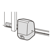
Details electrical and mechanical specs for MT/30/2 and MT/38/1 gearmotors.

Pre-Installation Motor Checks

Gate Angle and Distance Checks

Essential checks for gate angles, distances, and stop positions before motor installation.

Mobile Pin Position

Ensures the mobile pin is correctly positioned relative to the rear connection point.

Provisional Motor Installation

Bracket Positioning Calculations

Calculation of distances B and C for bracket positioning based on opening angle.

Provisional Rear and Front Bracket Fixing

Steps for temporarily fixing the rear and front brackets onto the gate and post.

Final Installation and Manual Operation

Final Motor Bracket Fixing and Release Mechanism

Steps for final bracket welding and mounting the release mechanism.

Manual Gate Operation During Power Failure

Instructions on how to manually move the gate in case of a power outage.

Control Unit Installation - Positioning and Cover

Control Unit Positioning

Guidance on where to position the control unit for optimal installation.

Cover Setting for Right Opening

Instructions for inverting the cover opening side of the control unit.

Control Unit Mounting and Wiring

Wall Mounting and Cable Inlet

Instructions for mounting the control unit and routing cables.

Wiring Advice and Box Operation

General wiring precautions and procedure for opening/closing the unit box.

Wiring Diagram

Electrical Connections Overview

Diagram illustrating the electrical connections and terminal functions for the system.

Motor Force and Electrical Connections

Motor Force Adjustment

How to adjust motor force using the control unit's potentiometer.

Motor Electric Connections

Specific wiring instructions for connecting motors to the control unit.

System Earth Connection

Procedure for establishing the earth connection between the motor and the home system.

Microswitch Settings Part 1

Gate Configuration and Deceleration Speed

Microswitch settings for gate logic and deceleration speed adjustments.

Final Closure Stroke and Electric Lock Release

Settings for final closure stroke and electric lock release stroke activation.

Microswitch Settings Part 2 and LED Signals

Start-Up Torque and Deceleration Settings

Microswitch settings for start-up torque and deceleration activation/deactivation.

Gate Movement Logic and LED Signals

Configuration for gate movement logic and explanation of LED indicator functions.

Control Unit Programming - Two-Leaf Gates

Work and Deceleration Time Programming

Step-by-step programming for opening/closing times and deceleration for two-leaf gates.

Safety Warning for Programming

Warning regarding temperature effects on force setting and programming repetition.

Control Unit Programming - Single-Leaf and Reclosure

Single-Leaf Gate Programming

Step-by-step programming for opening/closing times and deceleration for single-leaf gates.

Automatic Reclosure Programming

How to activate or deactivate the automatic gate reclosure function.

Radio Control Code Learning

Transmitter Microswitch Configuration

How to configure microswitches on specific mini transmitters.

Programming and Erasing Radio Codes

Instructions for learning and erasing radio control codes for transmitters.

Transmitter Expansion and Control Unit Specifications

Expanding Transmitter Capacity

Information on increasing the number of storable mini transmitters using SOG/4A.

CR;41 Control Unit Technical Specifications

Comprehensive technical data for the CR/41 control unit.

Photocell and Flashing Lamp Installation

P;10 Photocell Installation and Specs

Details on positioning, alignment, and technical specs for P/10 photocells.

Spherical Orange Lamp RZ;20 F Installation

Information on installing the RZ/20 F flashing light with built-in antenna.

Troubleshooting Guide

Serai KIT/30 F Specifications

General IconGeneral
Power supply230V AC
Motor voltage24V DC
Max. power300W
Max. torque30Nm
Protection levelIP44

Related product manuals