DAL 1965
Pag. 2/6
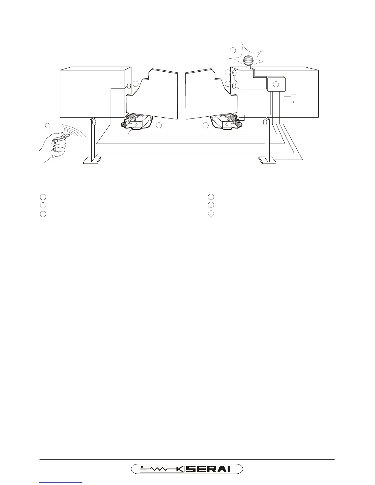
4 M/10 electric key
5 Pair of P/10 photocells
6 RZ/20 F Flashing light with antenna
1 MT/80/2
2 CR/41 electronic control unit with built-in receiver
3 OG/62 2-channel minitransmitter
Geared motor with foundation box
1
230V~
3x1,5 mm²
4 x 0,5 mm²
2 x 0,5 mm²
4 x 0,5 mm²
4 x 1,5 mm²
4 x 1,5 mm²
2 x 0,5 mm²
3 x 0,5 mm²
RG58 + 2 X 0,75 mm²
1
2
4
55
6
3
STANDARD INSTALLATION
Advice for wiring up in non-specialised environments.
1. Fit an omnipolar switch upstream of the system, choosing one with a gap of at least 3mm between the contacts. Or,
alternatively, use a 10A thermal magnetic circuit breaker.
2. Always make connections, of any type, with the system disconnected from the power supply, i.e. with the main switch
set to OFF (symbol “0”). The control unit, in particular, must never be connected to the power supply either during the
wiring up, or when fitting any expansion boards.
3. The following cables must be used for installation of the system:
22
- for the control unit, motor and electric lock power supplies: 1.5mm section for lengths of up to 19m, 2.5mm section
for lengths of up to 31m,
22
- for the flashing light: 0.75mm section for lengths of up to 3m, 1.5mm section for lengths of up to 19m,
- for the low voltage and current lines, (e.g. for the photocells, control buttons, electromechanical key, sensitive
22
edges and other safety devices: 0.5mm section for lengths of up to 50m, 0.75mm section for lengths of up to 100m.
4. Wire up the earth connection in compliance with legal provisions.
MT/80/2 I E