EasyManua.ls Logo

Server CSP - User Manual

Server CSP
8 pages
Print Icon
To Next Page IconTo Next Page
Loading...
MODEL:
CHILLED SERVER
WITH PUMP-
1 OUNCE
120V
Series 12G
94060
230V Continental Europe
Series 12G
94142
230V Australia
Series 12G
94143
230V United Kingdom
Series 12G
94144
PUMP, CSP-1 OZ
Series 12G
94040
EZ-CREAM
5/16 OUNCE
120V
Series 13E
94160
PUMP, CSP-5/16 OZ,
EZ-CREAM
Series 13E
94150
CSP
CHILLED SERVER
WITH PUMP-
2 OUNCE
120V
Series 12G
94050
230V Continental Europe
Series 12G
94145
230V Australia
Series 12G
94146
230V United Kingdom
Series 12G
94147
PUMP, CSP-2 OZ
Series 12G
94140
01672-REVE_102813_ENGLISH
Question and Answer IconNeed help?

Do you have a question about the Server CSP and is the answer not in the manual?

Summary

Safety Guidelines for Unit Operation

Electrical Shock Hazard Warning

Ensure unit is earthed or grounded using a three-prong plug.

Food and Safety Regulations Compliance

Adhere to local food and safety regulations for storage and serving temperatures.

Product Temperature Responsibility

Be aware of product temperature needs; Server Products is not liable for hazardous products.

Stainless Steel Corrosion Precautions

Avoid products containing acids, salt, or sauerkraut to prevent stainless steel corrosion.

Plastic Component Heat Sensitivity

Keep plastic parts away from high heat to prevent melting.

Unit Setup and Initial Operation

Pre-Use Unit Cleaning

Always clean the unit thoroughly before each use.

Power Connection and Verification

Plug the power cord securely into the unit and power source.

Unit Activation and Pre-Cooling

Turn the unit ON and allow it to pre-cool for 20 minutes.

Product Vessel Insertion

Insert the food product vessel into the unit basin; never place product directly in basin.

Pump Installation for Cooling

Install the pump to maintain maximum cold temperature.

Unit Take-Down Procedure

Power Off and Disconnection

Press the switch to 'OFF' and unplug the unit's power cord.

Removal of Pump and Vessel

Remove the pump and then the product vessel from the unit.

Filter Maintenance and Replacement

Recommended Filter Service Interval

Change or clean the filter at a minimum of once per month for optimal performance.

Accessing the Filter

Turn the unit over to access the filter holder and filter on the underside.

Filter Removal and Cleaning

Lift off the filter holder, remove the filter, and clean or replace it.

Cleaning Fan Cover Area

Wipe down the fan cover and surrounding area with a damp cloth.

Electrical Safety During Cleaning

Wring out cloths to avoid dripping water onto unit components.

Filter Reinstallation

Place the new or cleaned filter and replace the filter holder securely.

Pump Disassembly and Cleaning

Daily Pump Cleaning Requirement

Disassemble and clean the pump before first use and daily thereafter.

Pump Flushing and Rinsing

Flush and rinse the pump body to expel remaining product and water.

Disassembling Plunger Assembly

Remove plunger assembly and lid by turning locking collar counterclockwise.

Removing Cylinder and Discharge Tube

Remove cylinder and discharge tube from valve body by rotating counterclockwise.

O-Ring and Gasket Removal

Remove rubber gasket or O-rings from the valve body and discharge tube.

Disassembling Knob and Head Tube

Remove knob, locking collar, and head insert from the plunger assembly and head tube.

Piston Component Removal

Remove spring, washer, seal assembly, and O-ring from the piston.

Key Pump Cleaning Areas

Cleaning Stainless Steel Balls

Ensure all sides of the stainless steel balls are thoroughly cleaned.

Valve Body Cleaning

Clean valve body passageways and openings meticulously.

Valve Cover Disassembly

Removing Valve Cover

Remove the valve cover from the discharge tube by rotating it counterclockwise.

Removing Cone Washer

Remove the cone washer from the valve cover.

Caution Against Sharp Tools

Avoid using sharp tools during disassembly to prevent part damage.

Clean-In-Place Pump Procedure

Overview of CIP Process

Follow a basic four-step process: Clean, Rinse, Sanitize, and Rinse.

Detailed Cleaning Steps

Pump out residue, wash/rinse unit, flush internally, mix and pump cleaning solution.

Rinsing Procedure

Use clean water to flush and rinse the pump until all cleaning mixture is expelled.

Sanitizing Procedure

Mix sanitizer solution and pump it through the unit according to requirements.

General Pump Cleaning Guidelines

Daily Cleaning Importance and Warranty

Daily cleaning is crucial; failure to comply may void unit warranty.

Washing and Scrubbing Parts

Wash and scrub all parts with detergent and hot water; use supplied brushes.

Cleaning Agent Restrictions

Do not use abrasive cleaners, harsh chemicals, or tools that scratch surfaces.

Rinsing and Drying for Corrosion Prevention

Rinse thoroughly and dry stainless steel parts to prevent corrosion.

Sanitizing Food Contact Parts

Sanitize all food contact parts per local requirements and allow to air dry.

Valve Cover Assembly Instructions

Installing Cone Washer

Install the cone washer into the valve cover.

Installing Valve Cover

Install valve cover with cone washer onto discharge tube threading.

Securing Valve Cover

Rotate valve cover clockwise to secure it to the discharge tube.

Tool Usage Warning for Assembly

Do not use sharp tools for assembly to prevent damage to parts.

Unit Troubleshooting Guide

Troubleshooting Unit Not Cooling

Check power connection, unit switch, power source, and filter status.

Pump Troubleshooting Guide

Low or No Product Dispensing

Check for stiff pump, blocked parts, or product that is too stiff.

Inconsistent Portion Control

Inspect gaging collar for damage or improper installation.

Pump Not Returning to Top Position

Inspect spring for damage or breakage; replace if necessary.

Pump Dripping Issues

Ensure product is not causing expansion or dripping from the pump.

Pump Assembly Instructions

Plunger Assembly Steps

Assemble plunger with seal O-ring, seal, washer, spring, head insert, and collars.

Knob Installation on Plunger

Install and secure the knob onto the plunger assembly by rotating clockwise.

Pump Body Component Assembly

Install O-rings, assemble cylinder and discharge tube onto valve body.

Lid and Collar Installation

Install the lid onto the pump body and secure it with the locking collar.

Plunger and Cylinder Securing

Install plunger into cylinder and secure by rotating locking collar clockwise.

Comprehensive Unit Cleaning

Daily Unit and Pump Cleaning

Disassemble and clean unit/pump daily; failure to do so may void warranty.

Electrical Safety During Unit Cleaning

Avoid water exposure to electrical parts; never immerse or use pressure sprayers.

Washing Product Vessel and Pump

Wash product vessel and pump daily with detergent, rinse, and dry.

External Surface Wiping

Wipe external unit surfaces with a damp cloth and dry with a soft cloth.

Sanitizing All Food Contact Parts

Sanitize all food contact parts per local requirements and allow to air dry.

Cleaning Plastic Components

Hand wash plastic parts only; keep away from high heat.

General Service, Repair, and Returns

Contacting Customer Service for Support

Contact Server Products customer service to request a Return Authorization Number.

Merchandise Return Policy

Returned items must be new, unused, within 90 days, and subject to restocking fees.

Server Products Service Department

Service department offers prompt repairs, typically shipped the day after receipt.

Ordering Replacement Parts Information

Provide model, part, series numbers, and description when ordering parts.

Server Products Limited Warranty

Equipment has a two-year limited warranty; check website for full details.

Overview

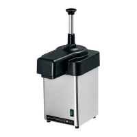
The Server Chilled Server with Pump is a versatile dispensing unit designed to maintain and serve food products at safe, cold temperatures. It is available in two main configurations: a 1-ounce pump model (94060 for 120V, 94142 for 230V Continental Europe, 94143 for 230V Australia, 94144 for 230V United Kingdom) and a 2-ounce pump model (94050 for 120V, 94145 for 230V Continental Europe, 94146 for 230V Australia, 94147 for 230V United Kingdom). An EZ-Cream 5/16 ounce model (94160 for 120V) is also available, with corresponding pumps (94040 for 1-ounce, 94140 for 2-ounce, and 94150 for 5/16 ounce EZ-Cream).

Function Description:

The Chilled Server is designed to keep food products cold and ready for dispensing. It uses a pump mechanism to dispense product in controlled portions. The unit is intended for continuous operation, acting like a refrigerator to maintain consistent cold temperatures, thereby eliminating the need for pre-cool periods if left on continuously. A temperature strip on the side of the product vessel allows for monitoring of the internal temperature.

Important Technical Specifications:

  • Voltage: Available in 120V and 230V configurations to suit various international power standards.
  • Pump Capacity: Available with 1-ounce, 2-ounce, and 5/16-ounce (EZ-Cream) pump options.
  • Product Vessel Capacity: Maximum capacity of two (2) quarts. Overfilling should be avoided.
  • Material: Constructed primarily from stainless steel, a durable material for food serving and storage. However, certain products (acids, alkalines, chlorine, salt, sauerkraut, Au Jus sauces) can corrode stainless steel.
  • Filter: Features a replaceable/cleanable filter for optimal cooling performance. Server Products Inc. offers a pack of 5 replacement filters (86067).

Usage Features:

  • Safety Guidelines:
    • The unit must be earthed or grounded, requiring all three prongs of the cord plug to be connected to a power source.
    • Users must be aware of the product being served and the required holding temperature to prevent hazardous conditions. Server Products Inc. is not responsible for serving potentially hazardous products.
    • Never immerse the unit in water or any liquid, and avoid using water jets or pressure sprayers, as this can damage electrical components.
    • Do not place plastic lid, cover, top, or chiller block insulation assembly near high heat, as it can melt.
  • Unit Set-Up:
    1. Plug the cord into a power source, ensuring secure connections at all points (unit, adaptor, outlet).
    2. Press the switch to the "ON" position.
    3. Allow the unit to pre-cool for 20 minutes. For best performance, keep the unit on continuously.
    4. Remove the pump.
    5. Insert the product vessel into the basin. Food product must always be inside the product vessel; never place food directly into the basin.
    6. Install the pump to maintain maximum cold temperature.
  • Portion Control: Gaging collars are used to ensure consistent portion control. Users should inspect gaging collars for damage or improper installation if portion control is inconsistent.
  • Troubleshooting:
    • Unit not cooling: Check cord connections, power availability, unit "ON" status, fan operation, and filter cleanliness.
    • Pump dispenses little/no product: Clean the pump. Check if the product is too stiff or contains solids.
    • Pump plunger not returning to top: Inspect the spring for damage (bent or broken) and replace if necessary.
    • Pump drips: Clean the discharge tube with supplied brushes. Ensure the product is not being heated by external sources, which could cause expansion and dripping.

Maintenance Features:

  • Daily Cleaning (Unit):
    1. Turn the switch to "OFF" and unplug the unit.
    2. Remove the pump and product vessel.
    3. Wash and rinse the product vessel and pump with dishwashing detergent and hot water. Dry thoroughly with a clean soft cloth.
    4. Wipe external surfaces of the unit daily with a clean damp cloth and dry.
    5. Sanitize all food-contact parts according to local sanitization requirements. Allow parts to fully air dry to prevent condensation.
    6. Plastic lid, cover, top, and chiller block insulation assembly are hand-wash only and not dishwasher safe.
  • Daily Cleaning (Pump):
    1. Disassembly: Pump out any remaining food product. Wash and rinse the outside of the pump. Flush out and rinse the inside of the pump with warm water until only water flows from the discharge tube.
    2. Remove plunger assembly and lid by turning the locking collar and discharge tube nut counterclockwise.
    3. Remove cylinder and discharge tube by rotating counterclockwise.
    4. Remove rubber gasket/O-ring from valve body.
    5. Remove small O-ring from discharge tube (carefully to avoid damage).
    6. Remove knob from plunger assembly by rotating counterclockwise (hold head tube firmly, spring pressure will release knob).
    7. Remove locking collar from head tube.
    8. Remove gaging collar(s) if used.
    9. Remove head insert from head tube.
    10. Remove spring from piston.
    11. Remove washer from piston.
    12. Remove seal assembly from piston head (carefully to avoid damage).
    13. Remove O-ring from inside seal (carefully to avoid damage).
    14. Valve Cover Disassembly: Remove valve cover from discharge tube by rotating counterclockwise. Remove cone washer from valve cover. Avoid using sharp tools for disassembly.
    15. Cleaning: Wash and scrub all parts with dishwashing detergent and hot water daily. Use supplied brushes to clean confined areas (cylinder, discharge tube, valve body). Avoid abrasive cleansers, scrapers, steel pads, steel wool, or cleaning tools that can scratch surfaces. Do not use cleansing agents with high concentrations of acid, alkaline, chlorine, or ammonia, as these can corrode stainless steel or damage plastic parts. A nontoxic glass cleaner can be used for stainless steel.
    16. Rinsing: Fully rinse all parts thoroughly with clear water to prevent corrosion.
    17. Drying: Dry all stainless steel parts with a clean soft cloth regularly to prevent corrosion from accumulated elements/minerals in tap water.
    18. Sanitization: Sanitize all food-contact parts according to local requirements. Allow parts to fully air dry. Parts are dishwasher safe.
  • Clean-In-Place Procedure (Pumps):
    1. Clean: Pump out food product. Wash and rinse outside. Flush inside with water. Mix 2 oz (5 mL) dishwashing detergent with 1 quart (.95 L) hot tap water (approx. 110°F/43°C). Operate pump repeatedly with this mixture until all is pumped through.
    2. Rinse: Place pump into 2 cups (.5 L) hot tap water (approx. 110°F/43°C) and operate repeatedly until all water is pumped through.
    3. Sanitize: Mix one 1 oz (30 mL) packet of KAY-5 Sanitizer/Cleaner (EPA REG NO. 5389-15) with 2.5 gallons (9.5 L) of room temperature tap water. Place pump into this mixture and operate repeatedly until 1 quart (.95 L) is pumped through.
    4. Rinse: Place pump into 1 cup (.24 L) hot tap water (approx. 110°F/43°C) and operate repeatedly until all water is pumped through.
  • Filter Maintenance: Change or clean the filter at a minimum of once per month for best cooling performance.
    1. Perform unit take-down.
    2. Ensure unit is "OFF" and unplugged.
    3. Turn the unit over to access the filter holder and filter on the underside.
    4. Lift off the filter holder by pulling it from one edge.
    5. Remove the filter and clean or replace it. The filter can be cleaned with hot water and dishwashing detergent, then fully rinsed.
    6. If necessary, wipe down the fan cover and surrounding area with a cloth dampened with dishwashing liquid or mild sanitizing detergent. Ensure the cloth is wrung out to prevent dripping water into the unit, which can cause electrical damage.
    7. Place a new or cleaned filter over the fan cover.
    8. Replace the filter holder.
  • Assembly (Pump):
    1. Plunger Assembly: Install seal O-ring inside the seal (apply lubricant). Install seal assembly onto piston head (apply lubricant). Install washer onto threaded end of piston. Install spring onto threaded end of piston. Install head insert inside head tube (beveled edge facing inside). Install gaging collar(s) and locking collar onto head tube by sliding them on (locking collar threading facing gaging collar(s)/flared end). Install head tube assembly onto piston assembly. Install knob onto plunger assembly and rotate clockwise to secure (hold head tube firmly, compressing spring).
    2. O-Rings and Pump Body Assembly: Install small O-ring onto discharge tube (apply lubricant, be careful not to damage). Install silicone gasket or O-ring into valve body (apply lubricant; if silicone gasket, flat side facing up toward cylinder). Install cylinder onto valve body (rotate clockwise, press down firmly). Install discharge tube onto valve body (rotate clockwise, press down firmly).
    3. Lid and Locking Collar: Install lid onto discharge tube and cylinder assembly (hole on lid onto cylinder threading). Install plunger into cylinder and secure by rotating locking collar clockwise.
    4. Valve Cover Assembly: Install cone washer into valve cover. Install valve cover with cone washer inside onto discharge tube threading. Rotate valve cover clockwise to secure. Avoid using sharp tools for assembly.

Warranty:

All Server Products equipment is backed by a two-year limited warranty against defects in materials and workmanship. For complete warranty information, visit www.server-products.com.

Service and Returns:

Before sending any item for service, repair, or return, contact Server Products customer service for a Return Authorization Number. Merchandise returned for credit must be new, unused, not more than 90 days old, and subject to a 20% restocking charge. Electrical parts are not returnable. Server Products maintains a fully staffed service department for prompt repairs.

Server CSP Specifications

General IconGeneral
BrandServer
ModelCSP
CategoryKitchen Appliances
LanguageEnglish